


Click on any image that has a border to enlarge. -
The USS Orleck DD-886 in 1/96th Scale
(Copyright 2006, used with permission by Warship Models Underway)
I had a 1/96th mostly complete scratch-built Fletcher DD gathering dust for about 20 years, as I could not find enough info or photos of the ship that I had originally intended to model. Having found some time for the hobby again recently I thought why not convert it? I had always thought the Gearing FRAM DDs were attractive ships and had participated in events that shaped my life. First as a youngster during the early days of the US space program I remember seeing them on TV during Mercury and Gemini recovery operations. Some years later I served as a Navy Aircrewman and the Gearing DDs were there 24/7 and would have come looking for us if we ended up ditching. I also saw pictures of Loren Perry's USS Vogelgesang (DD 862 Vogelesang) many years ago and thought it was a fine model, inspirational. Loren was editor of the Scale Ship Modeler at the time (now the proprietor of Gold Medal Models, maker of etched brass fittings for model ships). With these thoughts going through my head (and a few evenings of surfing) I found many photos of Gearing FRAM DDs and a set of plans on the web to base the conversion on. A recent trip allowed me to visit the USS Joseph P. Kennedy Jr. at Fall River, Ma. (DD850 USS Joseph P. Kennedy Jr). After banging my head and bumping my shins on the many hatch combings, I was hooked! The FRAM conversion project would commence after returning home.
The "Joey P", as the J. P. Kennedy is called, seemed to have plenty of sponsorship and be in very fine condition. I found out that the USS Orleck (DD 886 ORLECK) was under restoration at Orange, Texas (where she was originally built during WWII). The USS Orleck had a distinguished service career, including during in Vietnam and later served with the Turkish Navy in 1982, renamed Yucetepe until being generously donated to the Southeast Texas War Memorial and Heritage Foundation in 1992. The ship was returned to Orange, Texas in 2000 and has been under going restoration since. Quite a bit of help is needed because the ship was damaged during hurricane Rita (Orleck vs. Rita) and it is awaiting repair and possibly a new homeport. Contact the Orleck Museum staff at the following URL if you are moved to do so:
http://www.ussorleck.org/Support.asp
I thought that building a model the Orleck might help stir some interest and sponsorship for the restoration of the ship. Plus, Texas being a lot closer to Arizona where I live than Massachusetts it would be more convenient to travel to if I needed more detailed photos of the ship and maybe help chip some paint! So, the USS Orleck was decided on as the Gearing FRAM DD to model.
The Fletcher DDs and Gearing DDs have the same length to width ratio (L/W) although the Gearings are a bit larger. Knowing this I thought of simply building the new super structure, adding twin rudders and four bladed props and end up with nearly a perfect 100th scale model, but could not find enough fittings in that scale. Moreover, the model would be about 2 inches too short if I had the opportunity to sail with other modelers in 1/96th scale. So 1/96th it would have to be. I bought a set of Gearing FRAM plans on eBay in 1/192nd scale and had them enlarged to 1/96th for patterns.
Gearings are longer than Allen Sumner class DD's, Sumner's being wider than the Fletchers that they were based on (I have read somewhere that the last couple Fletchers had twin rudders as installed on the Sumner's and Gearing's). Having decided on the scale it meant that I would have to both lengthen and widen the hull from 47 X 4-7/8 to 48 7/8 X 5-1/8 inches. I decided to lengthen the ship first, and then widen it, which would provide a continuous, full-length keel for strength when the conversion was done. The hull would have to be lengthened about 2 inches and then widened about � of an inch.

I marked a centerline down the bottom of the hull to use as a reference during reassembly. Then, the widest part of the hull was located at the lowest point of the deck shear (curvature of the deck edge when viewed from the side) and marked a line all the way around the hull athwart ships (across the hull). A new razor saw made short work of the 20-year-old ply, spruce, epoxy and fibre-glass cloth. With the hull parted into two, there was no turning back; it was time to insert something other than air into the gaping holes at the center of the ship! A plug came to mind.
NOTE
The pattern and new frames where marked and cut very carefully to match the inside of dimensions of the old hull shape. The 1/32nd inch ply used to sheet the hull does not allow much room for error if the fit of the plug is poor.
I then rubbed pencil lead around the inside edge of the hull at the cut-line athwart ships and placed a sheet of paper over the opening, pressing the paper onto edge of the leaded surface. This transferred the inside shape of the hull to the paper which I cut out for the new frames pattern that included the keel and stringers notches as used for the old model. Next, I marked 1-inch tall standoffs onto the tope (deck end) of the pattern to use in assembly of the plug onto a building board. After cutting out the pattern I checked it against the ends of the cut on the hull. I went through a couple patterns before it was close enough. Next, I drew around the pattern and marked out four new frames onto 1/8th inch birch ply from which to build a constant-section plug (The Gearings section plug inserted into their Sumner hulls was used to provide extra volume for more fuel and equipment).
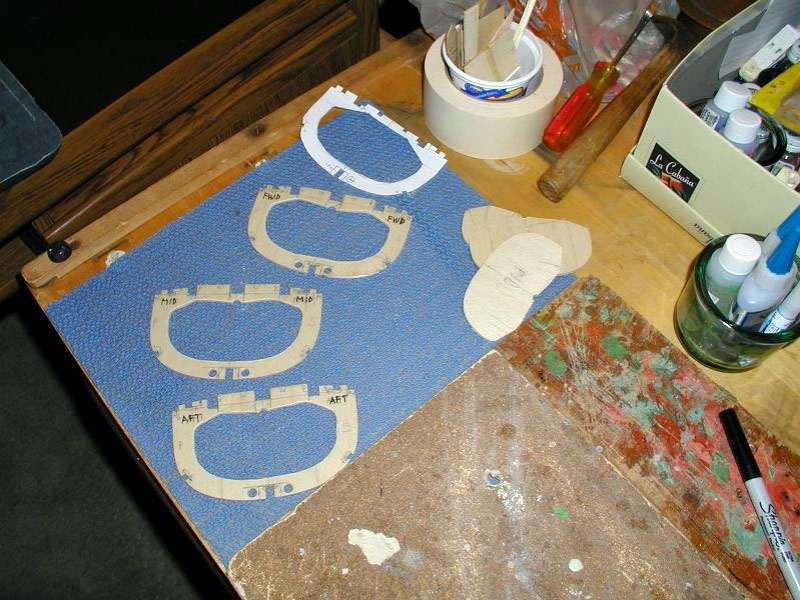
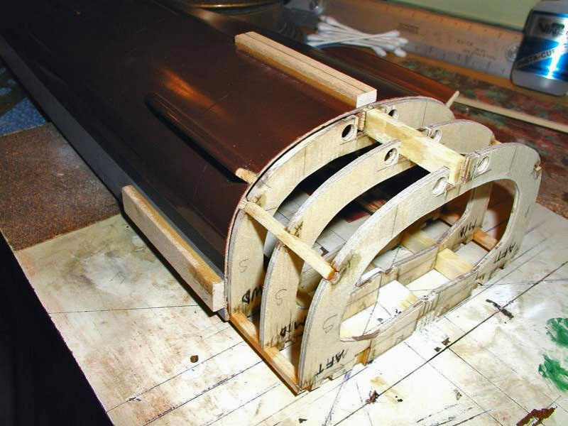
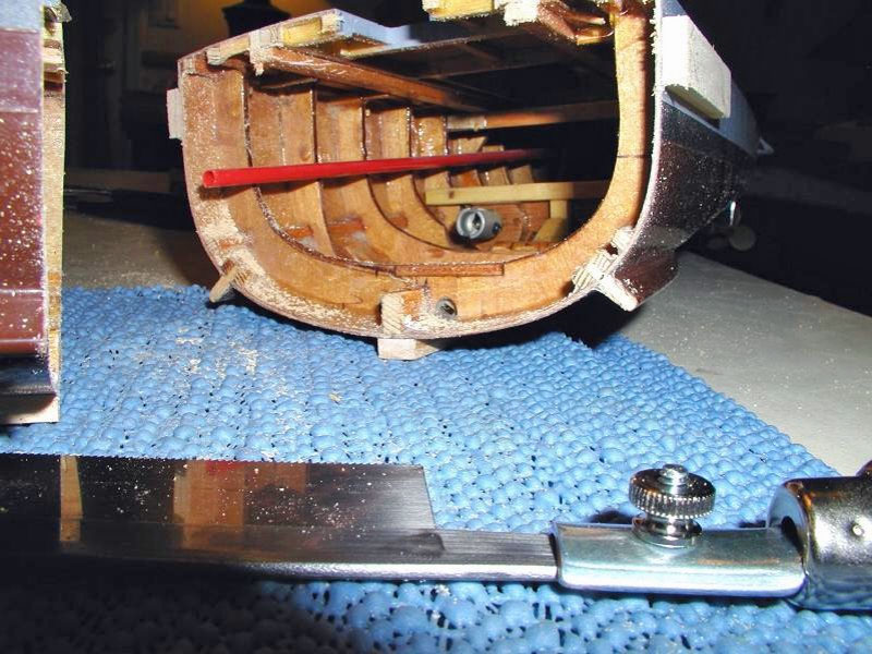
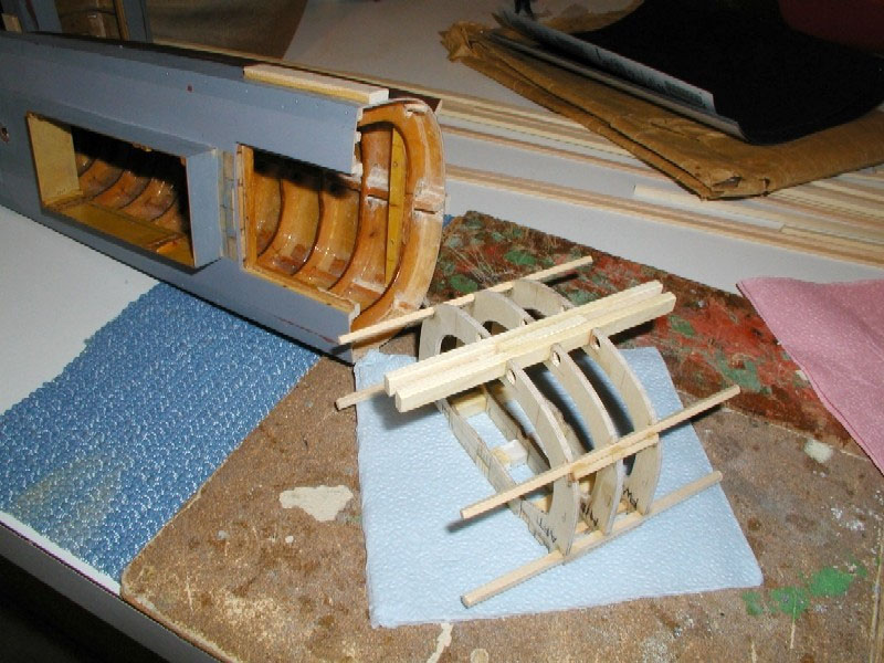
After cutting out the frames I checked them for fit and to make sure that they were as near to identical as I could reasonably make them on a rickety old jigsaw. I pitched out a couple that just weren't right. I then marked out the spacing on the good frames and a centerline on a flat sheet of wood that served as the building board (no curve or twist allowed!). The frames were then super-glued upside down on the standoffs onto the wood at proper intervals for a two-inch long plug along a centerline marked on the board. They were carefully squared-up in all directions to make sure that the plug would fit into the hull straight so that no curve would be built into the keel after it the hull is reassembled. The new keel and stringers were super-glued into place and cut-flush with the ends of the plug end-frames. Notches were added right next to them where additional stringers and keels were added that are long enough to extend two-frames distance into the old hull on both sides of the plug to provide a good mechanical connection for strength in the assembly when completed. This resulted in the plug having 3 keels, a stub that only extended to the ends of the plug and two more, one on each side of it that would extend into the old hull. The stringers ended up with only a single companion each.
Probably the single most time consuming and challenging part of the project was to drill and then file out the holes in the end two-frames of the old hull (two frames back from the cut) to accept the extended stringers and keels of the plug. I used a long drill and slowly drilled right next to the existing stringers and keel in the old hull halves. Then small square jewelers file were used to enlarge and shape the drilled holes to tightly accept the stringers and keels of the plug. The 20-year-old epoxy was very hard to file through, but equipped with a dust mask and mini-vac I finished the job in a couple hours. The files had to be cleaned several times as the epoxy caked onto them and they did not cut well when caked-up.
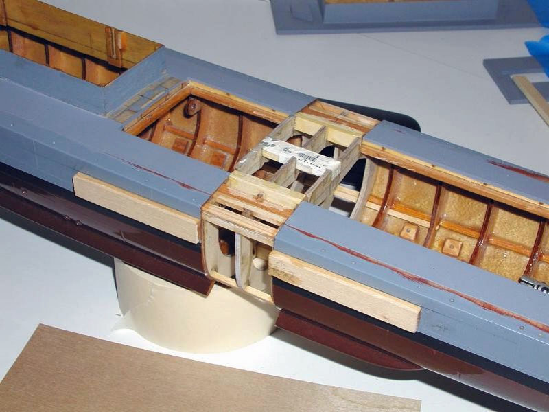
Working slowly and carefully during the construction of plug and in the preparation of the old hull-halves was rewarded by an almost snap-fit of the plug into the hull ends. It was nearly self-aligning. I checked the vertical and longitudinal alignment of the keel for the full length of the hull on the outside along the centerline marked before the hull was cut in half with long straight edge. I also made a full length tracing of the deck edges in plan view (from the top) and folded the paper down the centerline. Holding the paper up to the light showed where one side bulged out a bit more than it should (the lines did not match up just right). Just a little adjustment here and there brought the deck edges and keel into line. I also checked the hull for twist to make sure the deck athwartships was level (checked with a small line level. Again, more adjustment with the files and tweaking of the parts made the twist disappear. Using super glue I began tacking the hull ends to the plug, constantly checking for straightness, twist, and bulge until the hull was once again a straight integrated structure. Take your time if you do this. Again, this step is very important to ensure the hull will turn out "right" and be worth the effort of the conversion in the end.
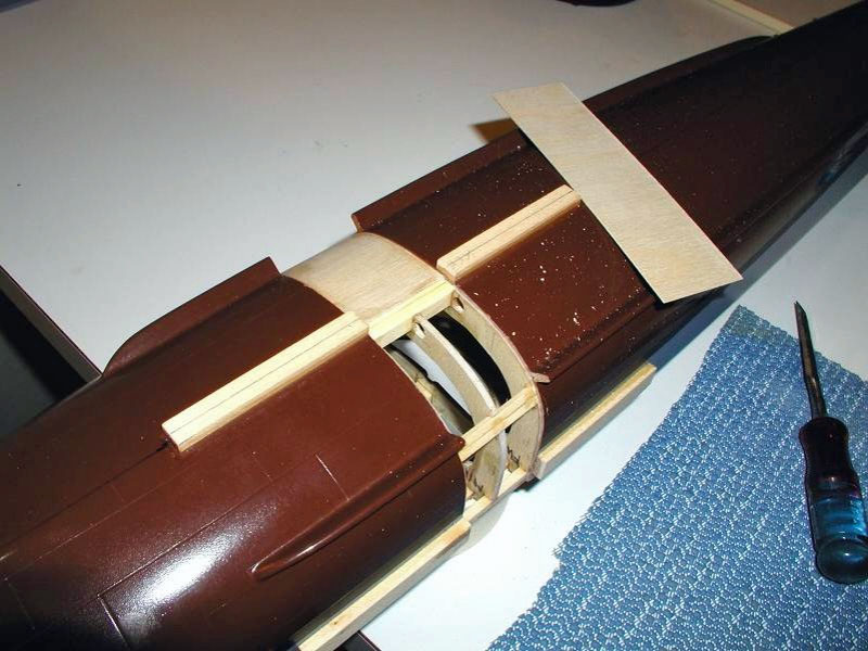
Once the hull had been re-joined I sheeted the plug with 1/32nd inch ply as had been done on the old hull, wrapping the ply tightly around the plug and onto the adjacent old frames (half their width had old sheeting removed to allow the new sheeting to attach to them) with the grain running fore and aft, using superglue it was tacked and then glued into place. Very small holes (1/32nd or less) were drilled through the sheeting into the stringers and keels where they butted against the old hull sheeting. The small ends of flat toothpicks were inserted into the holes, breaking off the excess and applying super glue to bond it all back together. Again, more mechanical connection is used in addition to the glue to ensure a strong, stable, and long-lasting job. The gap in the external bilge keels caused by the addition of the plug were filled with new wood strips, shaped and "doweled" into place with toothpicks as above.
![]()

Back to Warship Models Underway
This page maintained by Kurt Greiner. Email me here.
This page viewed 294
Version 1.2
Last update 12/09