


Click on any image that has a border to enlarge. -
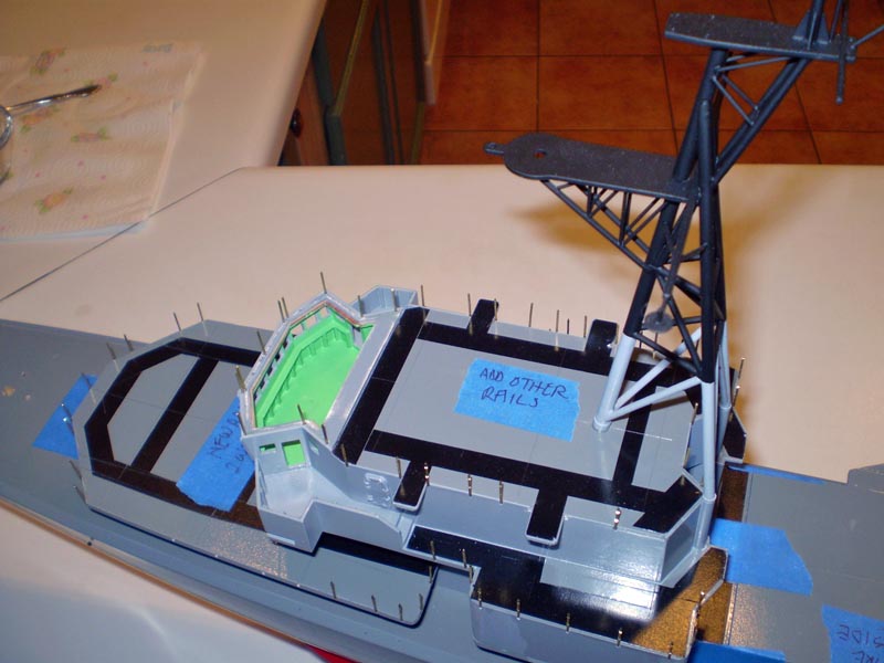
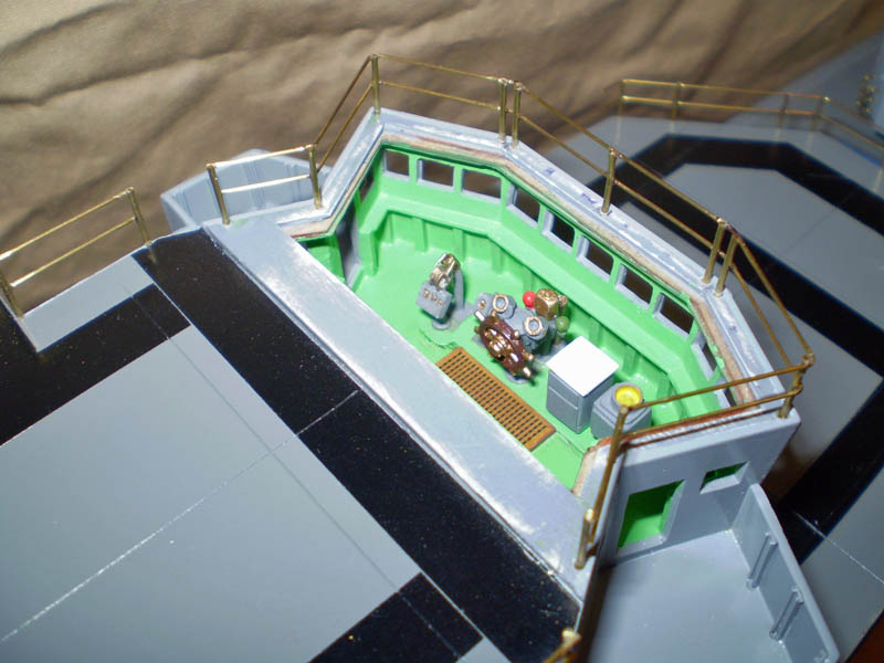
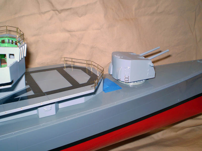
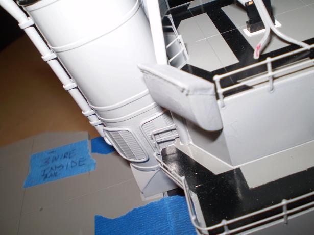
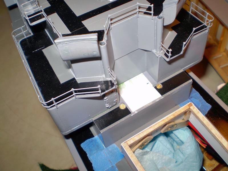
This picture shows the railing stanchions, and a repaint of the bridge interior.
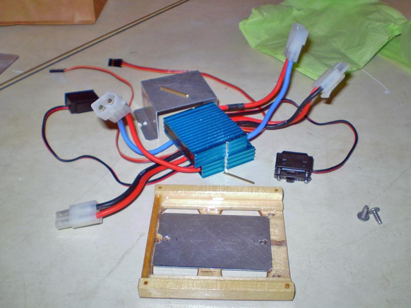
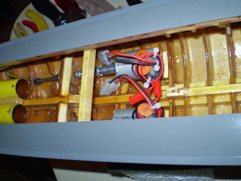
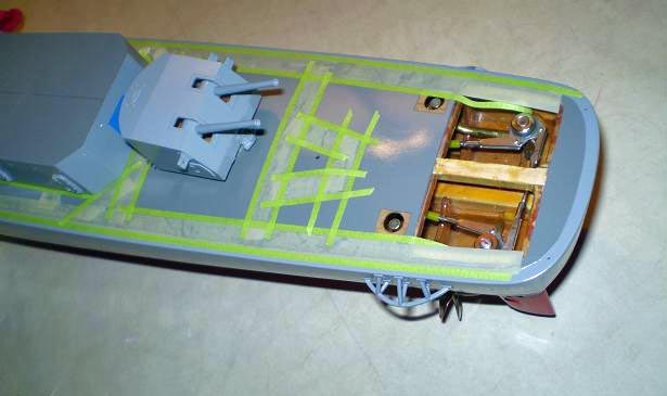
The speed controllers are mounted to an aluminum plate for extra cooling. Will check heat dissapation and current draw in a tub run. The motor connectors are on the top of the plate and face aft toward the motors. The battery connectors are on top of them and face forward toward the battery box.
The battery box has the wires and main switch tie-wrapped to it for ease of installation. It is temp, however, as I have found that the batteries are too hard to insert and remove for charging. A "length-wise (2X5) unit will be made up to replace cross-wise unit in the photos. That way All but the last two batteries will slide-in instead of snap-in. The model, as a Fletcher, was originally set up this way and it worked very well.
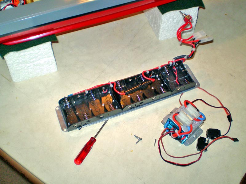
This photoshows the motor filter caps, the connetors for the speed controls, and a pair of test connectors, shown being used to run the motors off a 9v battery to adjust the motor alignment with them running (the mouting screws are adjusted until the motor RPMs peak and match each other (pic 013).
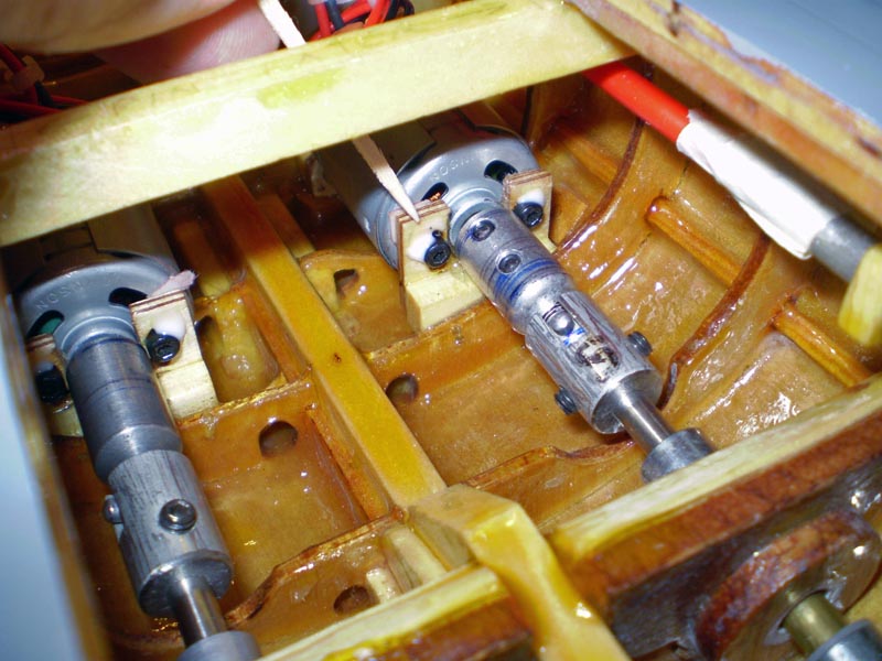

Pic 014 shows white glue being put on the screw to prevent them from backing out. A dot of superglue was put on each motor/mount to help hold things in place.
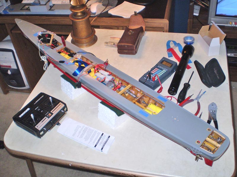
This shows the Mr. Science bench where the first run was done. It took awhile for the SCs to get programmed, but turn on fine now and run well in both directions with a good center off. You can see a piece of blue-ribbon coming out of the battery box. This is the "emergency-off" switch in case of smoke and flame. I checked the voltage polarity at the battery connectors before hooking them to the SCs, just in case!
November 5, 2007 update
Jerry writes:
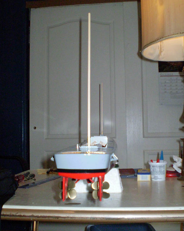
Here are a couple photos showing the installation of the Bridge Stanchions and railings. The other shows the vertical alignment of the turret azmiuth axis.
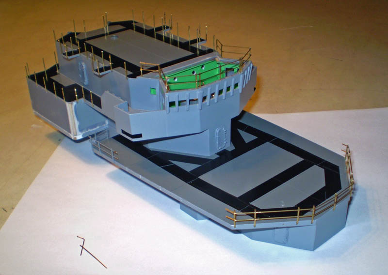
The weather is finally under a hundred most days and I may be able to get it launched once I get the water dams finished around the openings in the deck, and get some lanyards to connect the deck houses to the ship. Some fishing steel leader with quick clips at the ends and screw-eyes expoxied in the houses and hull deck beams should do it. Working on the lighting too. 1.5vdc bulbs from the model railroad hobby shop, with some mini-terminal blocks from Radio Shack to tie them all together seems to be working
The railings are super glued to the stanchions instead of being soldered. It is nearly as strong because the stanchions (0.032 brass wire) are notched to accept the railings (0.020 brass wire). An advantage is that a railing is more likely to simply pop loose instead of bending it and the stanchions around it. Repair is easy, just a dot of superglue and its fixed. No soldering iron, and no crumbing lead in high-salt environments. The remaining deckhouse and maindeck stanchions will be 0.032 brass, wire rope will be 0.010 monofilament line. gangway access chains will be twisted 0.010 soft copper wire, hammered slightly to make it appear like chain.
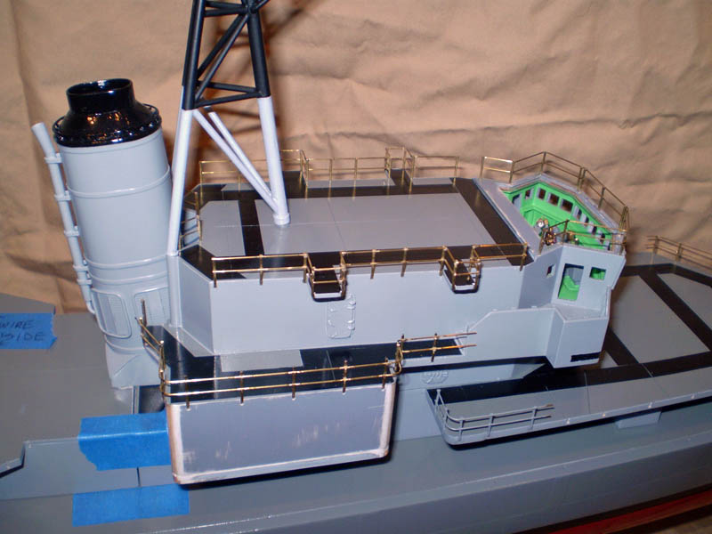
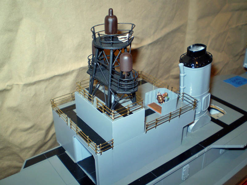

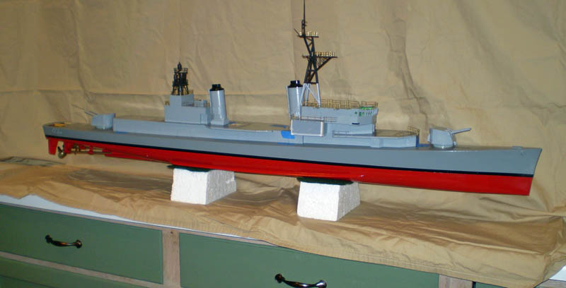
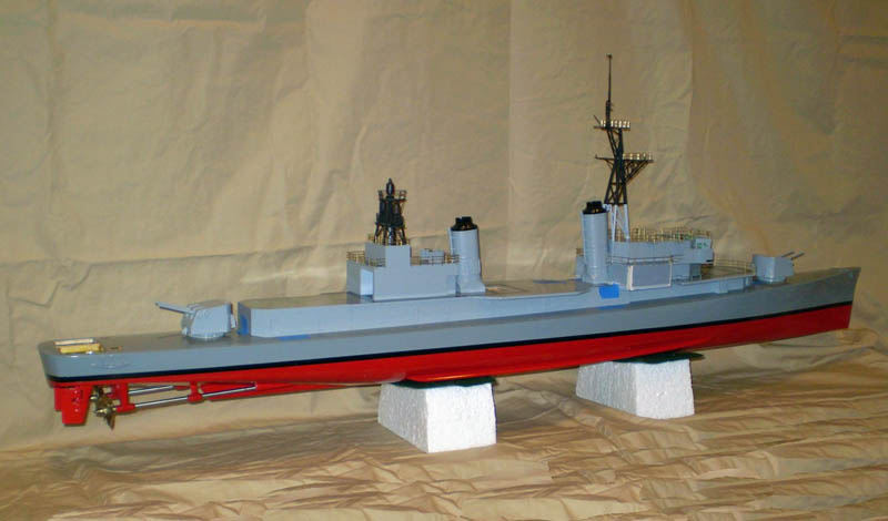
The uptakes are glued on. I have started installing the lighting: the nav lights are installed and the fixtures for the passageway and flood lights are being installed.
January 14. 2008 Update
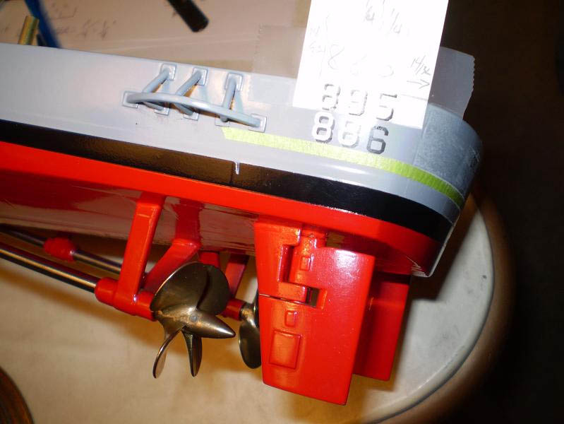
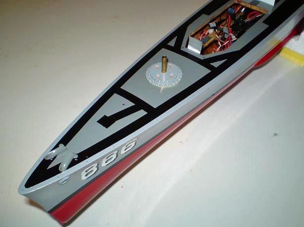
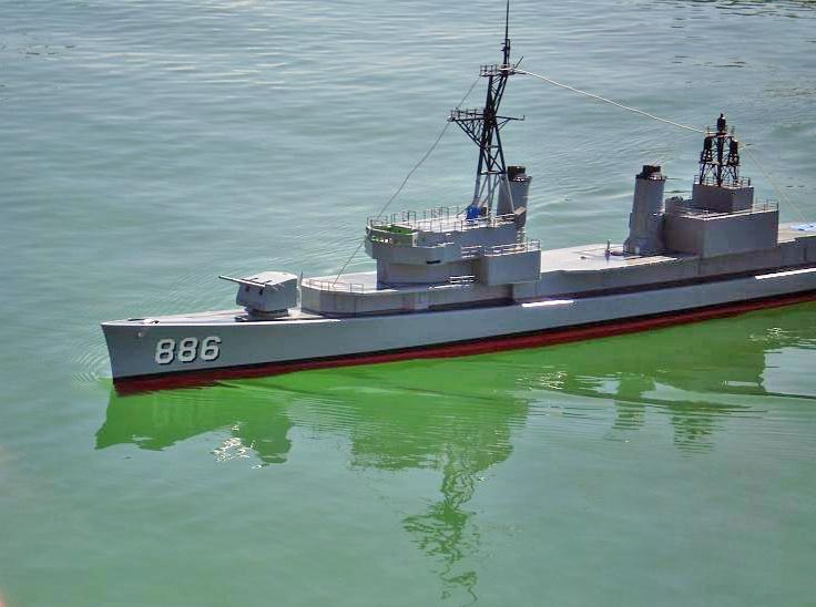
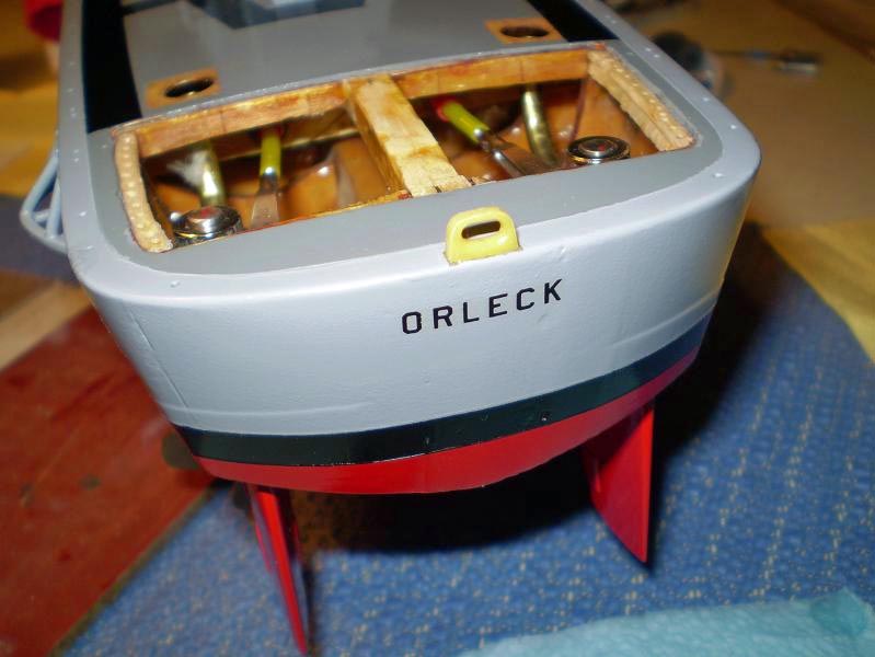
The stern numbers are dry transfers from the model RR store, in black, applied first, then white applied over the black, moved up 45 degrees to the upper left (a second white number was applied over the first because the black could be seen through it slightly.
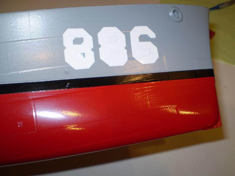
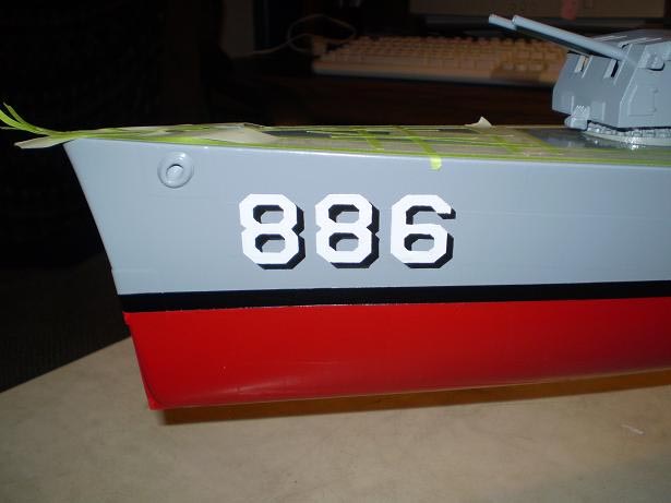
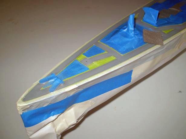
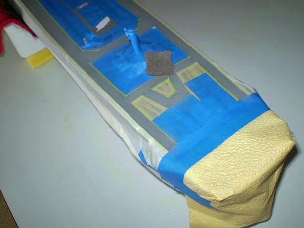
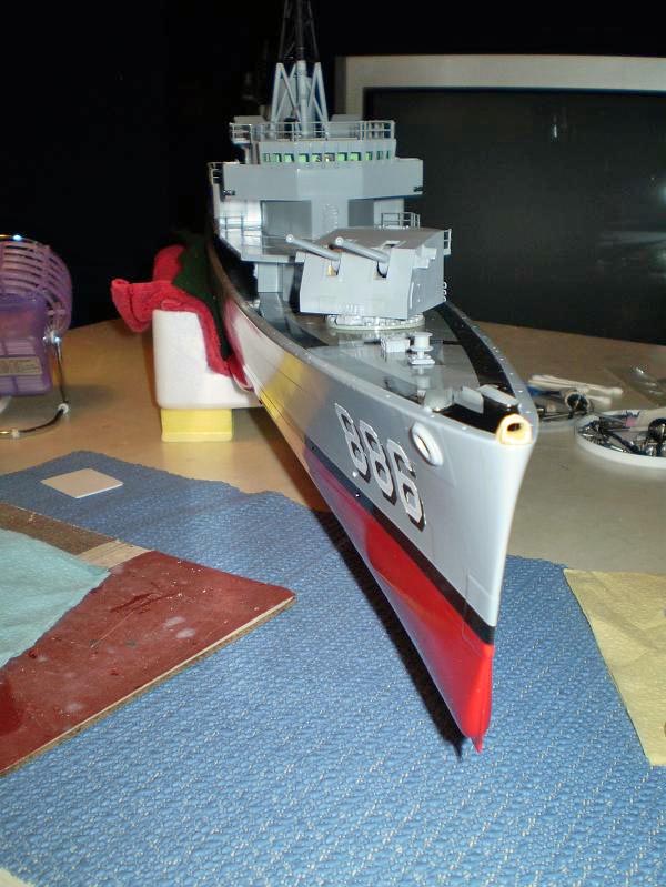
The bow numbers are painted on using Blue Painters Tape cut out on glass using stencils as guides.
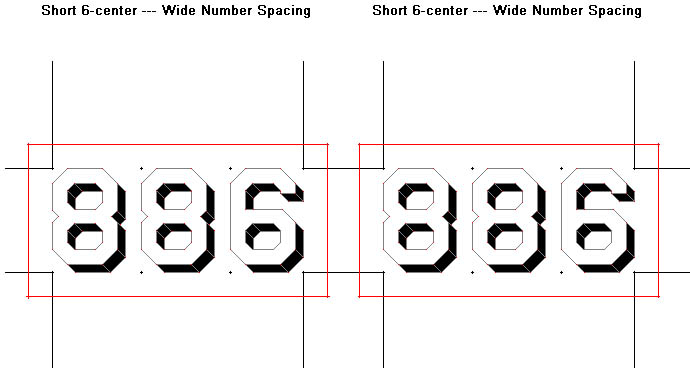
I first made the 886 numbers in MS PAINT, matching the size of the numbers on the McCandliss USS Gearing Plans that I have. They should be printed at 96X96 dpi for them to be the right size. Once they were printed I glued them onto 0.020 plastic sheet using spray contact cement to make the stencil. I held the stencil firmly to the the glass with regular masking tape around the edges so it would not slip. I then cut the numbers out with a new pointy Xacto blade (starting in the center) using a 6 inch steel ruler as a guide. Regular masking tape was taped to one side of the rule first, trimmed, and placed tape-side-down to keep it from moving around on the stencil while cutting. Moderate pressure was all that was needed (being darn careful not to slip!) to cut completely through the stencil to the glass on the first cut for a nice crisp edge.
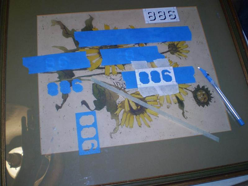
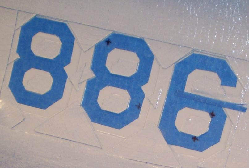
Once the stencil was cut out it was taped over the Blue Painters Tape that had been applied to the glass. Another new Xacto blade was used to cut the blue tape. I cut the outside of the numbers, including the shadow part, first, then cut out the innermost small parts (5 for 886), where the gray of the hull paint would show through. The large blue-stencil was then coaxed off of the glass using the Xacto blade tip and tweezers and applied to the hull. The inner small parts where then located inside the 8's and 6. All the tape was firmly pressed down and the hull gray inside the applied stencil was roughed up with very fine (gray) Scotch Brite. The area was cleaned off using more blue tape to lift the dust. The area around the outside of the applied blue stencil was masked off, painted white, and the tape removed right away. Once completely dry after a few days, the blue 8's and 6 part of the blue tape will be applied over the white in their respective place, another large blue stencil applied around the outside as before, and the black shadows will be painted.
February 5, 2008 update
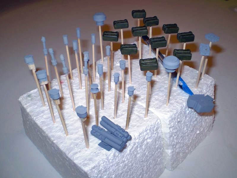
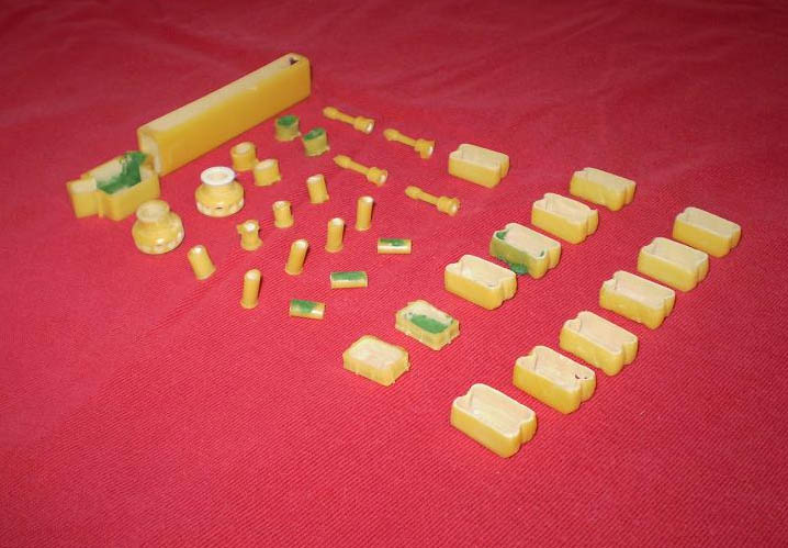

Here are some pics of part of Lee's resin DD850 fitting set. I hollowed them out to reduce weight. The rafts then had a thin balsa insert super glued in the back to cover the hole. I need to check on the raft color. I think they are to green, likely should be a dark gray. The dowels will be cut short and used as an alignment pin for the fittings.
February 14, 2008 update
The bow hull numbers are completed with the black shadows added.
The ASROC ready service magazine has been added to the right side of the aft superstructure deckhouse and the flagbags have been added to the aft end of the fwd superstructure deckhouse.
The main-deck walkways have been masked, roughed up with fine Scotchbrite, and painted.
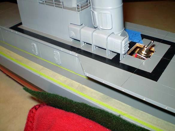
March 2, 2008 Update

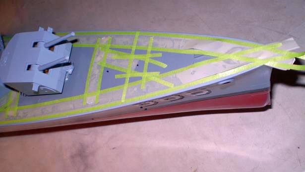
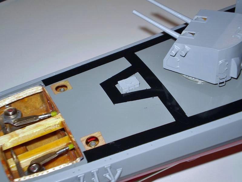
The tape being used to locate the forward deckhouse after the water dams where built.
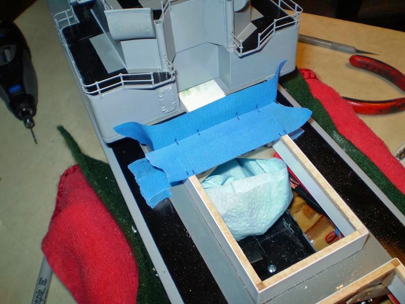
The small brass screws used to hold the forward deckhouse in place. I developed a single-point hold-down for the aft-deckhouse that I will convert the forward one to, eventually.
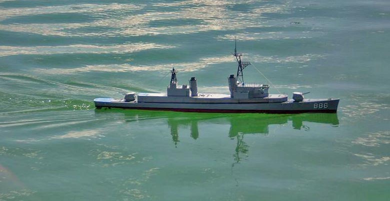
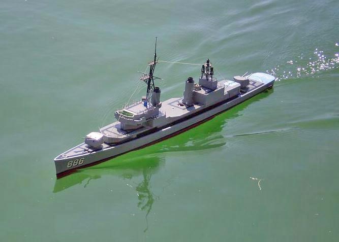
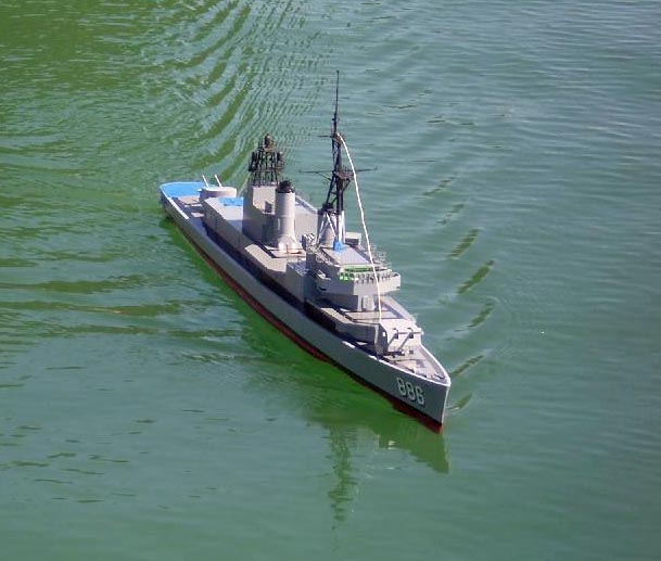
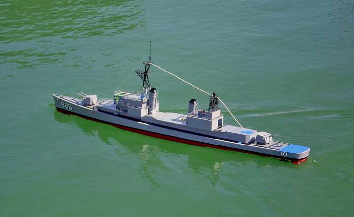
Well the big day arrived, the USS Orleck is operational. We took her to McCormick Lakes at Scottsdale for the event. The wind was up to about 20 knots at the south end of the lake with 6 - 10" chop. So we migrated to the north end where as you can see the water was a bit calmer. She sailed like a dream.

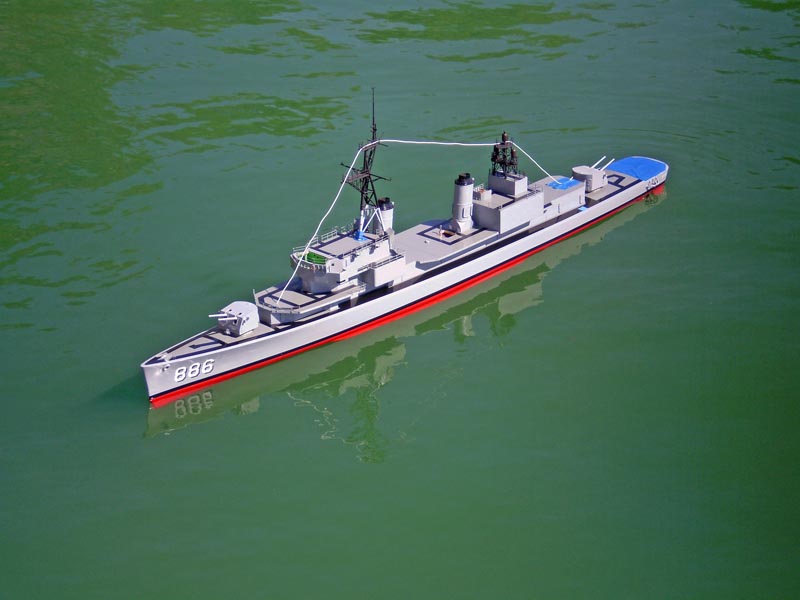
Here I am with the USS Orleck

4/14/08 Update
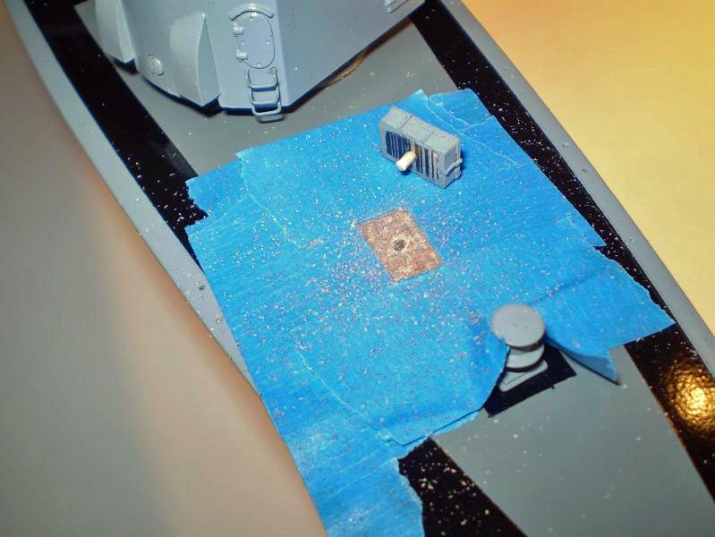
Here are several pictures of the first of Lee's Scale Shipyard fittings being installed on the USS Orleck: the fore and aft crew compartment hatches, the capstan, and the bow and stern chocks.
Since the model had already been painted I drilled a locating hole for each fitting in the deck and then used a couple layers of blue tape as a barrier and the Dremel tool and a sharp drill bit on slow speed to remove the paint down to the fibre-glass and epoxy. Some of the walkways need a little touch up with the paint brush. Time to bring out the deck-division!
The blue tape was then removed and a thin coat of medium (hardware store) viscosity super glue as applied to the prepped area on the deck, and then on the bottom side of the fitting. In both cases, the glue was not applied up to the very edge to allow some space for "squeeze-out" to keep the glue from overlapping onto the painted area adjacent to the fitting.
The fitting was then carefully aligned and pressed into place, soaking up any excess glue that did come out from under the fitting with a piece of 1/16th inch balsa strip with a chisel-point cut on to the end.
Ater installing, The bow and stern chocks were coated with a couple layers of super glue, the excess being soaked off with Q-TIps, to ensure that they were fully glued-down and to provide extra strengh for real mooring of the ship. They are pinned with 0.032 dia brass rod.
I am installing the big parts first so that by the time I get to the smaller fittings like the bits and other chocks, I will have made any mistakes with something that can be repaired easier.
![]()

Back to Warship Models Underway
This page maintained by Kurt Greiner. Email me here.
This page viewed 57
Version 1.17
Last update 12/09