


Click on any image that has a border to enlarge. -
Thin plastic sheeting (0.010 to 0.020) gets pretty floppy and soft "Way Out West" in the hot mid-day and afternoon sun. Its great for vacuum-forming but not for maintaining close scale dimensions by itself. Cheap vacu-formed model railroad mountains come to mind.
Thick (0.050+) sheeting is more stable, yet it may put so much weight onto a ship model that a DD in this scale might well be commissioned into the "silent service" instead of sailing with the surface fleet! No sense in having to over-ballast your ship just to keep it upright on the pond.
But, who wants to do lots of sanding and filling of wood grain to build a lightweight wood superstructure that can stand up to the heat better than thin plastic sheet? It can be done. I built the original Fletcher-DD deckhouses out of balsa and pine strip-wood, model aircraft style, and sheeted the frameworks with 1/64 ply. It was covered with ľ oz glass cloth and waterproofed the inside and several coat of primer filled the weave okay. They were light and have maintained their shapes very well over the years with no warp or twist, even to this day. BUT, they had to be cut very precisely and took a lot of time to build!
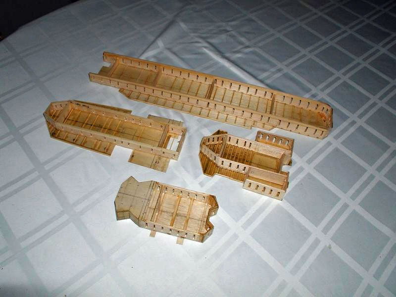
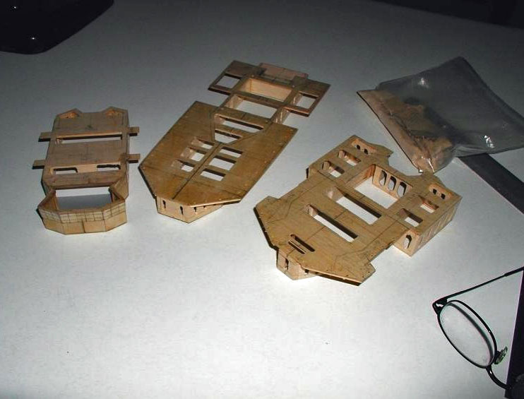


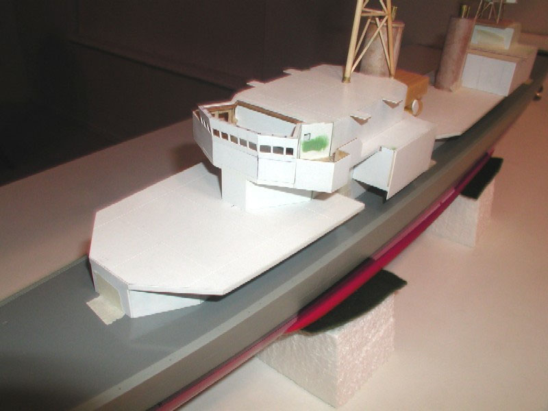
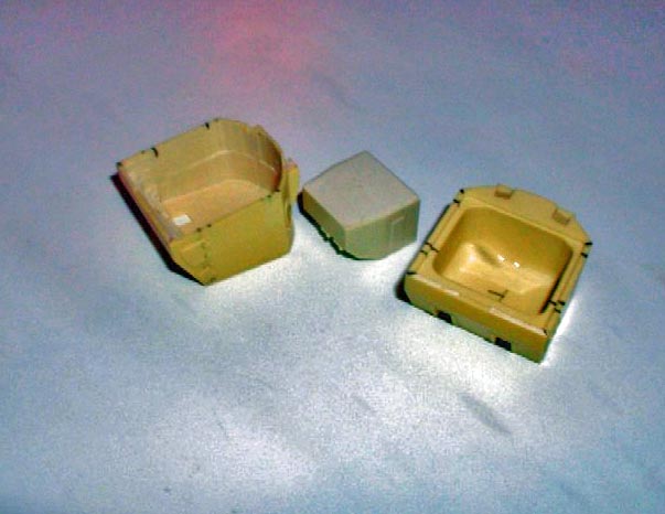
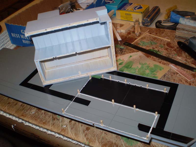
I tried something different this time around. The Gearing DD conversion uses simple 1/8th inch thick balsa sheet (planks) for the deckhouse sides (with basswood strips at the bottom edge of the house that fits against the hull deck to minimize the dents they would otherwise accumulate, and for stiffening). 1/32nd inch ply is used for the decking. The fit did not have to be perfect, as a little extra sanding or shimming here and there fixed anything that was not quite square or cutout right. They built fast. The sides and decks were routed-out at regular intervals for two reasons: top hamper weight reduction and to provide access for super-gluing the thin 0.010 to 0.020 plastic sheet to the wood.
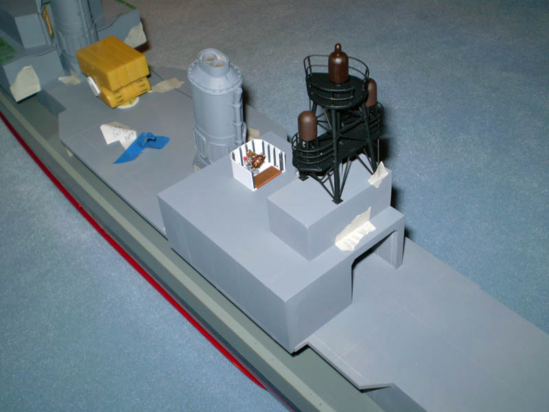
The bridge was built out of 1/32nd plywood and has been sheeted with 0.020 plastic sheeting. Basic bridge furniture and fittings will be installed, including helm, engine telegraph, binnacle, radar repeaters, pelorus, nav table, & etc.
For this method I use a layer of quilted, "non-lotioned", non-"pARfumed" bath tissue to act as a gasket between the wood and plastic sheet when bonding one to another with very thin superglue. The balsa provides a very stable foundation (stands up 'dimensionally' very well to the local high-temperatures) and forms a sturdy base for the thin lightweight plastic sheet to be attached too. The plastic sheet is paintable with little or no preparation! The bath tissue acts as a "carrier" and "reactant" during the gluing process. The balsa method worked so well I think I will recommend it to guy down the street who is building something called an 'airplane". Seems to think it will float on the air like ships do on water. Kinda nutty, but likeable. Original thinker.
Pre-sand both sides of the plastic sheet. Use a very-fine grit of Scotch-Brite on the paint-side, and 120 to 100-grit paper for the glue-side. Cut the plastic sheet and the bath tissue oversize for the area to be covered (about 1/8th inch for the plastic and about an inch for the tissue). If you choose to use this process be sure to do this step with lots of fresh air (outside), as the fumes can get intense because of the bath tissue! I use a fan, too, even though I work outside!
" Use a small flat-block (a flat-smooth brick will do) set on a table to use as a stable work area. Cover and smooth out two layers of plastic sandwich wrap over the "block". Superglue does not seem to stick very well to "SARANWRAP" which is beneficial for this process. Test it yourself just to make sure. Use something that works for you.
" Next, lay the bath tissue over the deckhouse wood and place the plastic over the tissue, aligning till it fits.
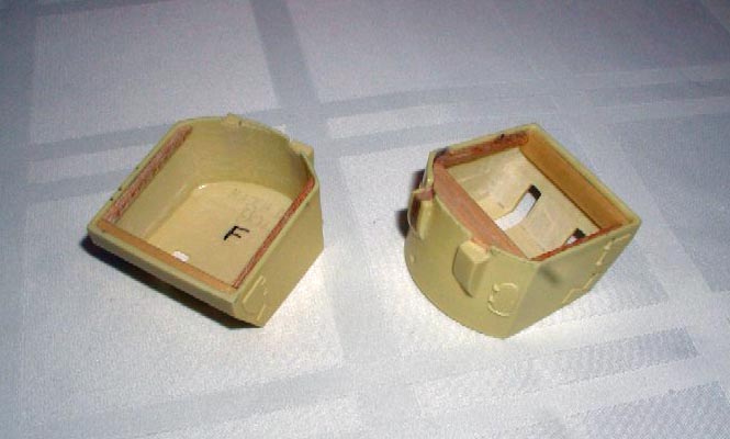
" Flip the part to be glued over, so the routed-side of the deckhouse-wood is facing up. You can see the tissue covering the plastic through the holes in the wood.
" Set the deckhouse with the plastic-side down (wood side up) onto the on the work "block" (make sure that the plastic has not shifted).
" Start gluing the plastic sheeting to the wood structure by applying thin (watery) superglue through the holes in the wood structure onto the exposed bath tissue. It wicks right in. Glue it all. BUT WATCH THE EXCESS and don't become permanently attached to your model!
" The tissue conducts the thin-superglue evenly and completely between the plastic and wood. Press the wood down onto the plastic, gently, to get full contact between the plastic/tissue/wood. Watch for glue squeeze-out.
" Be careful! The wood and plastic may become very hot! It seems that when superglue comes into contact with fine particles the reaction accelerates and the materials become hot. The finer the particle, the hotter it gets. The bath tissue is nothing but compressed fine wood-fibres and as a result a lot of heat is generated in the process.
" The net result is that the heat and glue bonds the plastic to the (wood) tissue, which spreads the glue very evenly onto the wooden deckhouse structure for a very well bonded system.
" The excess tissue sticking out from the edges of the deck house "wicks-up" most of the excess superglue for a relatively mess free job. Keep table napkins and Q-Tips on hand to mop up any mess or excess glue.
" Lastly, the next day, after leaving the glue to completely react and the fumes to disappear, trim the tissue back to the plastic, then trim the plastic back to the wood. Exacto, Sand, etc. Re-glue any places that may have missed out on glue, or been broken loose by trimming.
" Once all the wood is sheeted, waterproof the entire interior to stabilize the balsa and ply, as done for the hull interior using thinned long-cure epoxy method.
" Install fittings, doors, etc.
" Prime, thinly.
" Use Ultra-fine Scotch-Brite to break the surface of the primer.
" Dust off.
" Paint.
I ended up with a few dips and bumps using this method the first time around. But, since the routed-out areas in the deckhouse sides and decks approximate the framing of the deckhouses on the real ship it adds to the scale effect of the Gearing FRAM Converted DDs. They had nearly 20 years of service when they received the FRAM conversion and had seen a lot of action and time-at-sea, lots of visible distortion in the hull and deckhouses resulted. Dings, dongs, dips, and bumps within reason on the model are allowed. They are prototypical. No "dangs", though, please! They can take a long time to fix, like the time the original Fletcher model joined NAVAIR temporarily and decided to take a two-second flight to the floor. "DANG!!!"
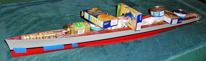
Weight and Ballasting:
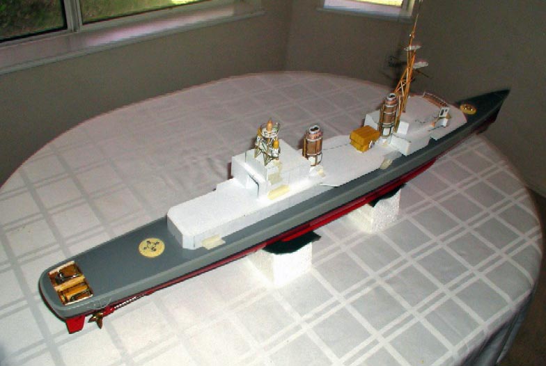
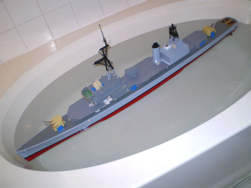
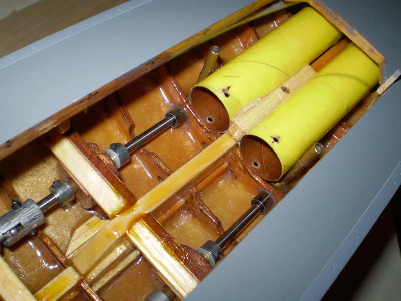
Before the film for my digital camera ran out I managed to get a photo of the ballasting experiment. Actual weight required to make the hull float at the scale waterline is 5.39 pounds of MAC, Olives, Tuna, Beans, etc. After ballasting I weighed all the items on a precision scale to arrive at the total weight. The heaviest item to be installed is the battery pack (2 each 12 volt ˝ "C" cell packs (1100 mah, weigh 8oz each) for 1 pound total. Each pack will power one motor through a separate, reversible, ESC. The Internet is a great place to find weights on products that you use. The battery packs are from (BATTERYSPACE.COM), and are fully assembled in shrink-wrap with wiring and connectors already installed. The remaining 4.39 pounds is for all the other things, including the ESCs, motors, radio, superstructure, primer, glue, paint, fittings, turrets, etc.
December 13, 2006 Update
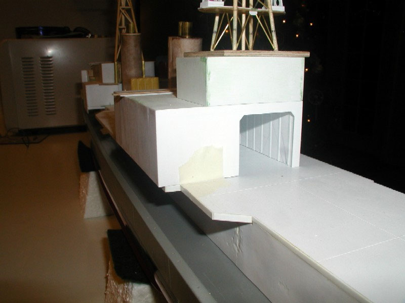
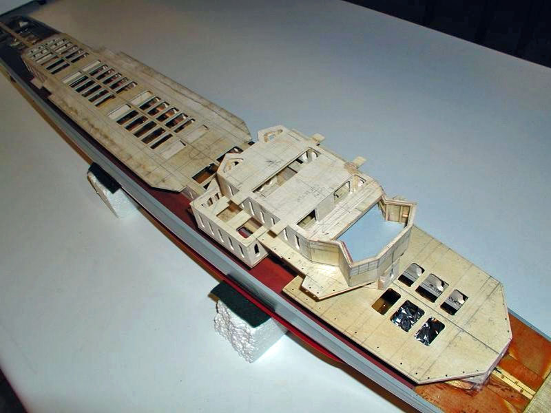
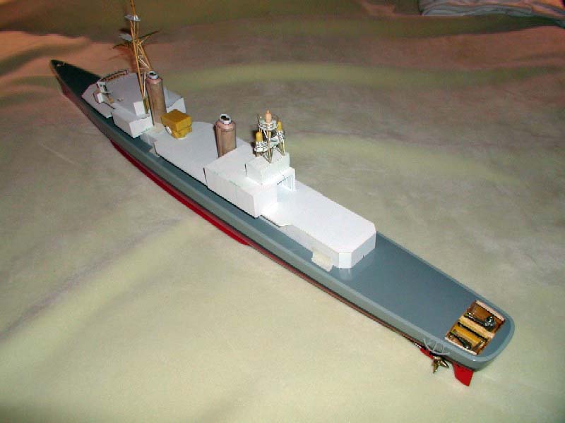
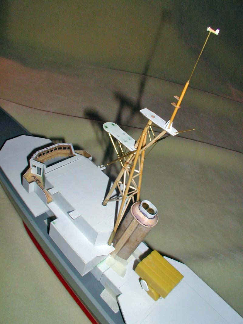
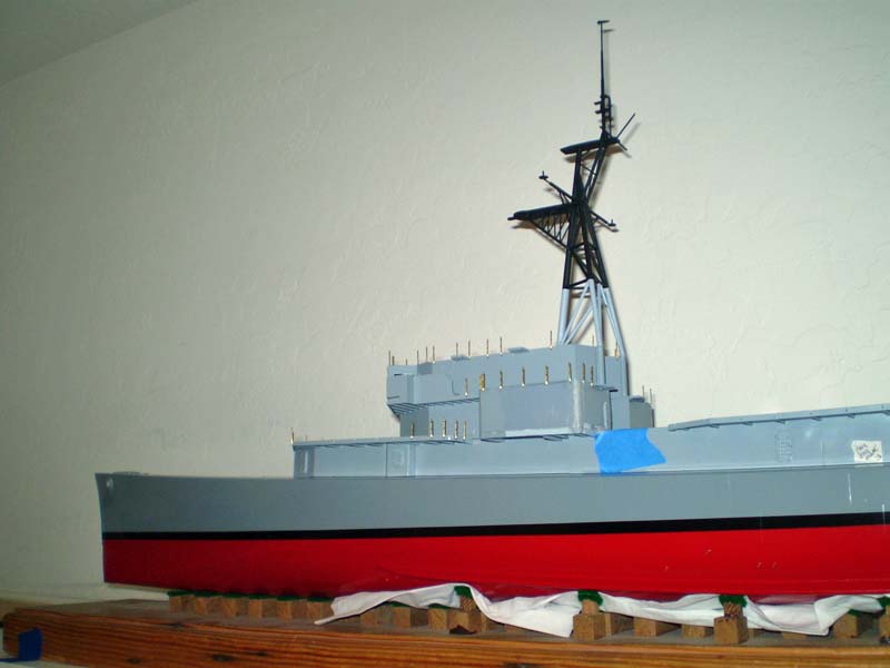
Port quarter view
Bridge plastic sheeting installed
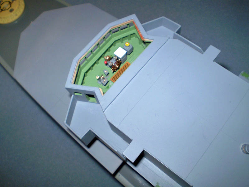
View of DASH hanger inside
The finely cast resin ASROC Launcher is from Lee Upshaw's SCALE SHIPYARD and was assembled as per the instruction set. In addition to the standard assembly I did "Swiss-cheese" each part with my Dremel Tool and a 3/32nd drill bit as a weight reduction measure with holes about 1/32nd inch apart. EVERYTHING got drilled: boxes, rotation unit, and the base (the outer boxes were drilled most of the way through, the inner boxes were drill all the way through). It was another out-doors task, as the resin shavings develop a static charge and stick to just about anything! A good paint mask and vacuum cleaner are a must for this job!
The missing-parts monster got the launcher's trunions (he lives under the workbench somewhere and secretly sells lost parts on the black market). I had to make new ones out of thick plastic sheet, thin plastic strips, and some pieces of bass tubing. The instructions and photos came in real handy here. The hand-grabs were made from 0.020 brass rod, bent "U-shaped" over a 3/32nd inch-wide form (Popsicle-stick) to make them all the same size. Holes where carefully marked in the ASROC rotation-unit and then a cut-off-common-pin was used as the drill-bit for the job. Slow speed was used.
The launcher went together very easily in about 2 hours. More than half of that was used in drilling all those holes!

ASROC Launcher
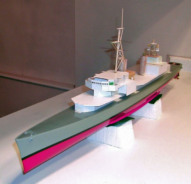
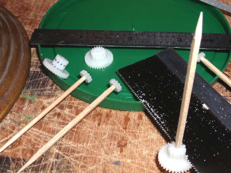
The Gearing FRAM masts consist of multiple steel pipes welded together with various cross-braces and platforms. The Foremast being a tri-pod affair, the aft mast has four legs. The model's masts are made from various sizes of dowels and round tooth-pics were used in the construction of the masts. Hardware stores, craft stores, and restaurants are a source for these. Square brass tubing and brass rod was also used for some parts of the masts. Superglue was used throughout the construction; using the "sewing needle eye" glue applicator located here http://wmunderway.mysite.com/cont/superglue/superglue.htm (excess being mopped up with Q-Tips).
Each mast was measured from the plans and a fixture for each was mapped out and constructed from handy material. The cheesy looking board that the foremast was built on is one of those never-throw-it-away pieces of thin wood, because it remains dead-flat, rain or shine, year after year. The aft mast was built on a small piece of scrap ply.
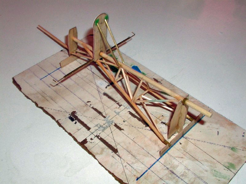
Foremast:
The foremast fixture was built horizontally and arranged so that the symmetrical aft legs were assembled first (flat on the board), then the main, taller, forward leg was aligned and attached to the aft legs with a stand-off at each end aligning it for the correct angle. In choosing the standoff lengths, arrange them so that the horizontal cross-braces are vertical to the board. This makes assembly easier and ensures that when the mast is installed on the ship that the horizontal braces are all parallel to the water line. These were pinned with brass pins between the mast legs and braces to add strength. A cutoff common- pin was used as a drill-bit. The diagonal braces were installed next. All the braces' ends were notched to ensure a close fit between parts for strength. The radar platforms were added and covered with sheet plastic on the top surface. Brass tubing and wire were used for the platform braces (brass rod will be used for the stanchions and railings). Lastly the top mast and signal yard was added. Excess glue was cut or filed away to keep the appearance scale. Doubler plates have yet to be added to some of the braces (these seem to have been added later in the life of some of the ships).
Foremast on building board
Aft Mast:
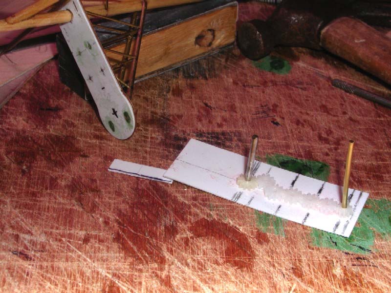
The aft mast was built vertically (as it would be mounted) by marking out the leg spacing on the board and drilling holes in the board were the supports were located, including a central, alignment, dowel. Then the platforms were made and assembled to the central dowel at the correct height (the upper platform had holes drilled where the four supports meet with it). The legs were inserted through the holes in the upper platform and the baseboard. Everything was lined-up and glue applied to the base and upper platform, then the lower platform. The leg-dowels where then trimmed flush with the base and top platform. As for the Foremast, brass rod was used for the braces, stanchions and railings (more on building railings later). The ECM antennas were assembled to bases built from styrene sheet and strip. I put a dowel or pin in everything so that it won't come loose later on and plunge to the bottom of the lake.
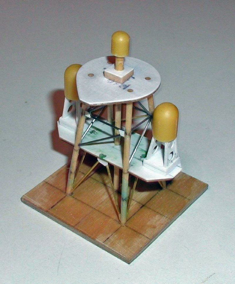
Aft Mast on building board
Once the masts were assembled they were cut way from the fixtures and cleaned up with jewelers files, emery boards, Scotch-Brite™ and a sharp Xactoknife. The wood was water-proofed with the thinned epoxy mixture by placing the masts in a large ZIP-LOC bag, adding about 1/4th of a cup of the epoxy mixture and slowly tumbling the sealed bag (DEFINITE OUTSIDE ACTIVITY!). Double bagging was used incase holes got poked in the inner bag. Once the masts were treated, they were dipped in lacquer thinner to remove excess epoxy and allowed to cure. I set them on a bed of toothpicks stuck into a block of styro-foam. Q-TIPs were periodically used to remove any excess that did pool and would give the part a blobby appearance. They will be Scotch-Brite'd lightly and dusted-off prior to painting,
January 27, 2007 update
February 7, 2007 update
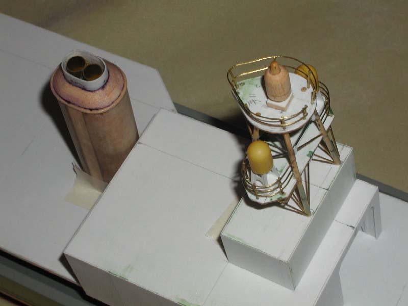
Boiler steam pipes:
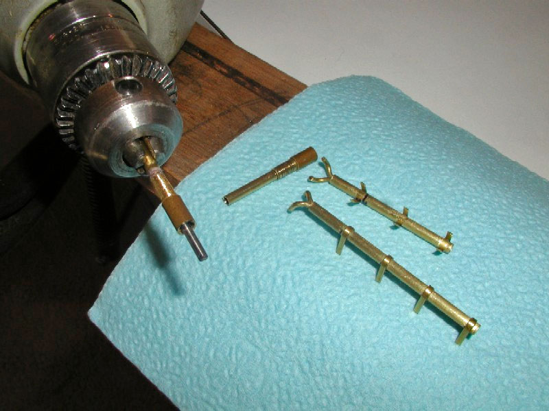
These were made from 3/32nd brass tubing for the main pipe and brass rod for the pipes where the come out of the funnel into the main pipe. For the pipe-top, nested 1/8th and 1/4th inch brass tubing, turned to a funnel shape using goggles, a drill motor clamped to a board, a mandrill to hold the part, and a Dremel Tool with a drum-sanding disk. The finished "top" was parted from the mandrill using a Dremel 1 inch cut off wheel. The whole thing was super glued together, including the brass mounting straps.
One pic shows" turning" the tapered steam pipe tops with my home-made lathe. Mydrill motor is clamped to a board and turns the part while a Dremel Tool (c) with a coarse sanding drum is used to do the shaping.
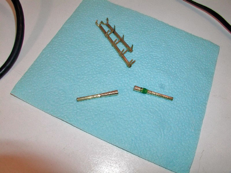
The next one shows the tops after turning and receiving a little Squadron GREEN STUFF (c) where thin spots of tubing broke away (3 telescoped tubes were super glued together, the innermost was kept long and worked as a mandrel to chuck into the drill.
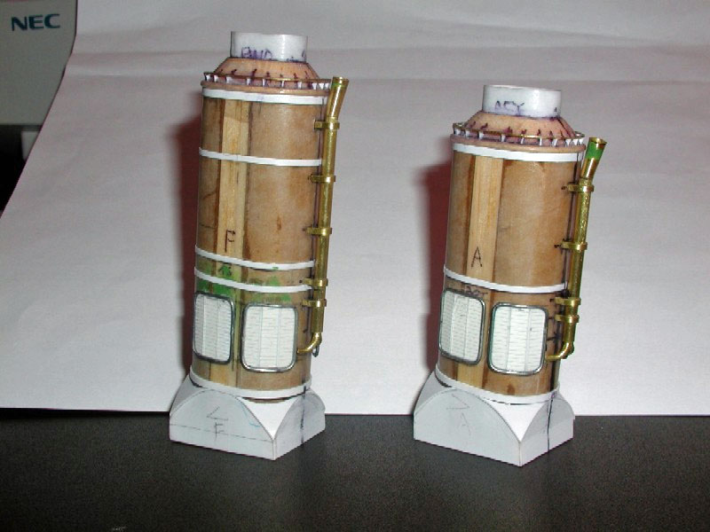
The last one shows the completed steam pipes attached to the aft end of the funnels. Also shown are the boiler air intake louvers.
The louvers are made from Evergreen (c) 0.050 thick clapboard-shaped plastic sheeting cut to size. The surrounds are made from 0.050 mild steel florist wire purchased from Micheals Art Store (c) and carefully bent to shape. The louvers were glued to the funnels first, then the surronds were sized and attached. This made it easy to handle the small parts.
I used Lee's HOW-TO tips on using the eye of a modifed sewning needle to apply the super glue (wine bottle cork makes a nice handle!) I use Q-TIPs to remove any excess glue immediately, and then brush the area with an old, fine, soft tooth brush to level and remove any glue build-up left behind. It works very well. A soft brush is needed to keep from dislodging the part. Brushes last a month or so before the glue build-up on them makes them useless.
Main section:
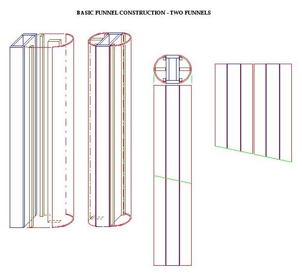
The funnels were made by building a long rectangular tube (open at the tops and bottoms) out of 1/32nd sheet, and from a model rocket cardboard tube split down the middle. The balsa tube as made long enough so that the two funnels could be made out of it. The cross-section is as wide as the funnel, and as long as the constant-cord (flat-sided) section of the funnels. Balsa strips were glued to the front and backsides of the rectangular tube near the edges so the rocket tubes would have something to be glued to. After the cut rocket tubes had been added a center stiffener was cut and glued in place. The assembly was then soaked on the inside with epoxy mixture and fibre-glassed on the outside with ľ oz cloth, using the same thinned epoxy. Once cured the assembly was cut at angle*, into two lengths, one for each funnel and balsa plugs were added into the ends.
*The angle sets the "rake" of the funnels. Note: when the funnels are nested together the tops are in a line with each other (see drawing).
Funnel bases:
The bases were made from 0.010 sheet styrene, cut to match the photos. The sides were glued on first, then the front and back. The curved top pieces were cut and fitted last. The funnels where flipped over and filled with un-thinned epoxy and Micro-Ballons to add strength while keeping the weight down.

Air intakes:
The air-intakes for the boilers were made from 0.050 sheet that was louvered on one side (model railroad stuff). The 8 pieces were cut and match-sanded, and each was lightly scribed, into 3 sections. They were glued onto the funnels using photos for reference and allowed to dry. Annealed 0.040 florists wire was used for the surrounds. It bends easy (easier than brass) and had no spring-back when you form it. These were added to he louvers after they were mounted on the funnels. The funnel is much bigger and easier to hold than the louvers by themselves.
After this the steam pipes were added to the backsides of the funnels. The Xacto knife was used to open slits into which the steam pipe mounting straps were inserted. Once other detailing is done (such as siren/platform(s), antenna cabling/supports) they will be primed and painted. Slightly lighter and darker grays used on the various parts will help the details to stand out.
April 4, 2007 Update
Gun Mounts
The turrets are from John Haynes and are cast resin, as is the gun director. They are accurate and come complete with cast metal barrels and resin bases. The turrets are hollow-cast, which saves on weight, but I chose to reduce the wall thickness to save on extra weight. I used a Dremel Tool mounted to the drill press stand to mill them out to a 1/16th inch wall thickness, down from 1/4th inch. Once milled mounting braces were installed inside the bottom 1/16th from the edge to allow the turret bottom to fit flush.
April 21, 2007 Update
Here are a few more in progress pics, Bridge wing Nav Lighting and the Bridge controls.
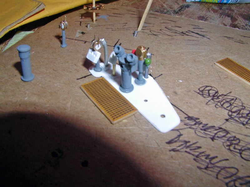
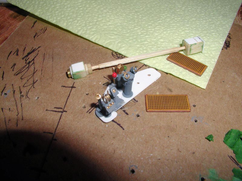


The Bridge Helm, Binacle, and telegraph are from BLUE JACKET, adapted for the DD. The objects at the ends of the toothpics are the bridge safe and the radar indicator. The gratings in the other photo are printed paper. The graphic was made in MS PAINT and was printed with a Laser printer. The paper was then super glued to a thin sheet of balsa and the edges were painted brown.
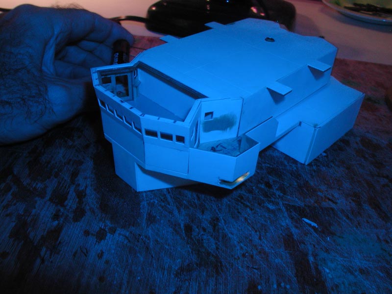
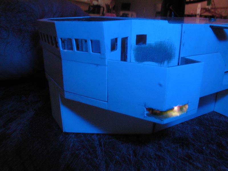
The bridge wing lighting test "Blue-shots" were shot with my digital camera with flash (2 layers of 3M(Tm) Painters Blue Tape, taped over the flash).
May 9, 2007 update
Bridge details added
July 2, 2007 Update
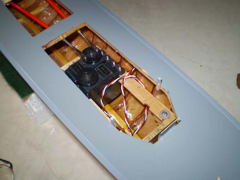
One of greasing the stuffing tubes with Hot Vaseline, from the bottom, up (Note: An air relief hole has been drilled in the stuffing tube at the top where the air accumulates, inbroad of the bearing to prevent hydraulic lock. This allows greasing of the tube with the shafts installed. Hole will be covered with a small square of plastic painted up like a Zinc). The rudder tubes were done the same way.
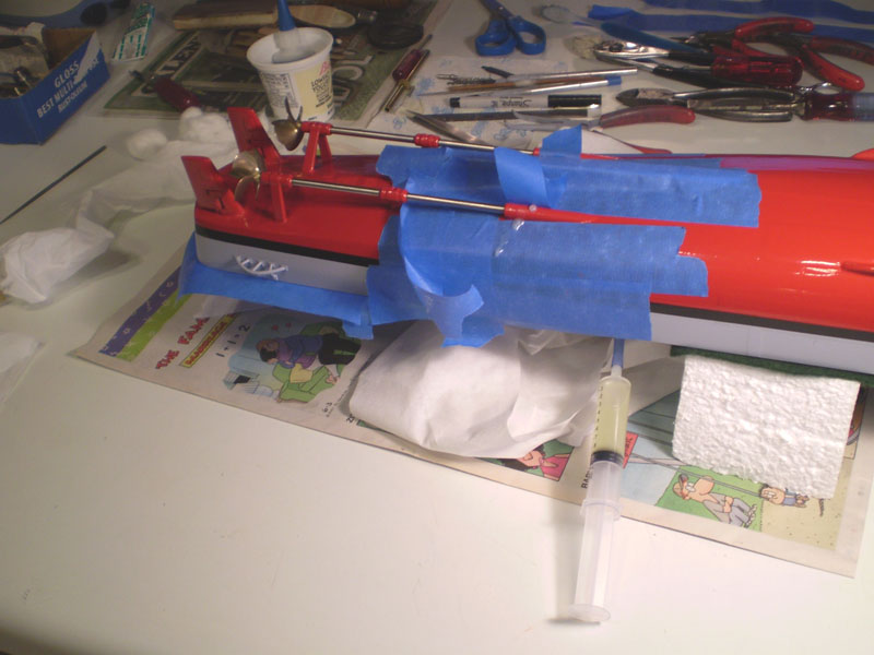
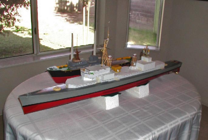
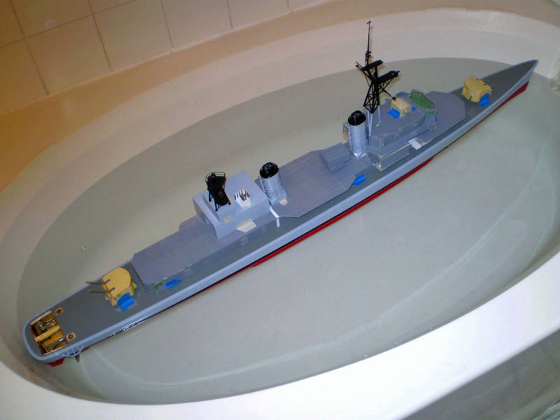
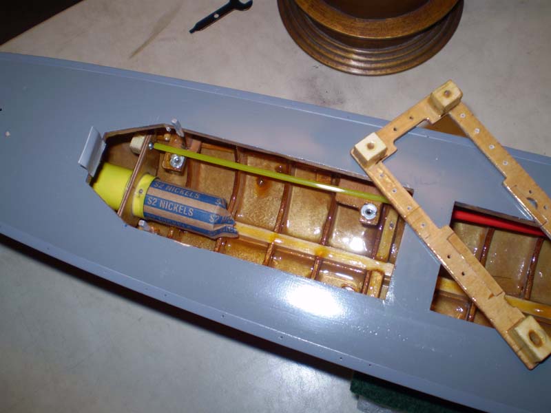
Other pics show ballasting tests taking place. With all radio, servos, batteries, speedc controllers, and motors installed, it took 3 rolls of Nickels (about 21 oz, 1.3 #) to bring the ship down to the bottom of the Boot-Topping. Some of that will go top side to finish out the fittings installation (maybe 4-5 oz), the rest will be made up of removable ballast in the bottom of the hull (the rolls of nickels or pennies).
September 1, 2007 Update
Some in progress pics on the Gearing DD conversion.
I made holders for nickel roll ballast, after the tub-test determined where the ballast was needed. All the ballast and batteries will be removed when the ship is in dry-dock between outings to make it easier to handle and less prone to warping. Also shown are the rudder and turret azmiuth servo mountings. Another servo may be added later to provide dull independent gun elevation control.
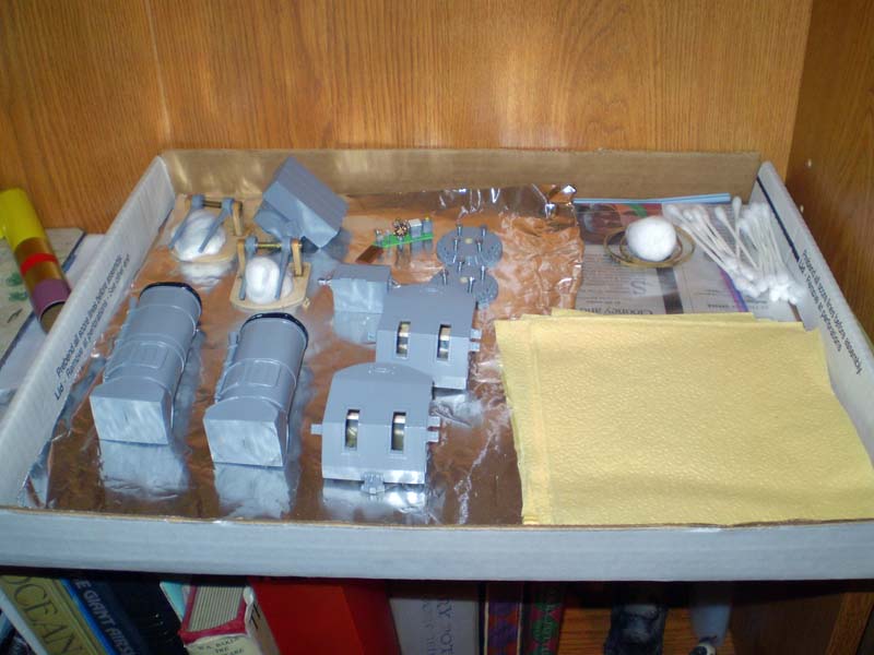
One of the pics shows the railing stanchions mounted, with the attendant railing groves filed in them. There is a shot of components painted and ready to be attached. Thinking about using screws instead of glue.
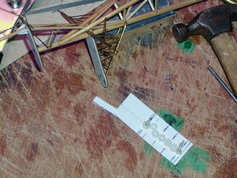
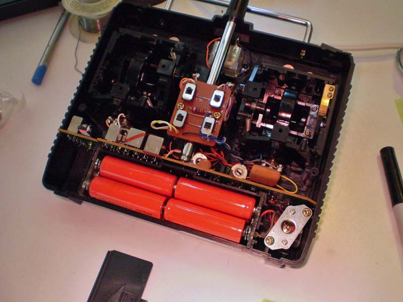
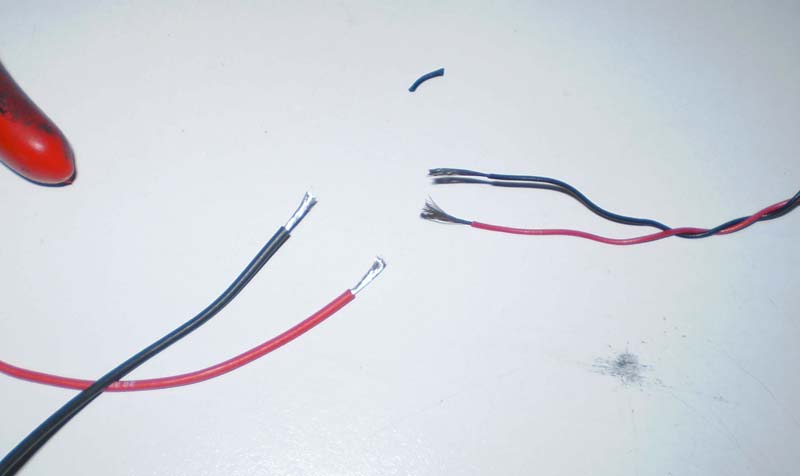
On the radio repair side, the Futaba5-ch radio is a 23 year old FM land frequency, "brand-new" radio. It has about 3 hours use total, all of it some 20 years ago, but needed some work! The transmitter NiCad batteries were left in it and the wires between the battery contacts an the ON/OFF switch were severely corroded. They were replaced and the battery contacts were removed and throrougly cleaned in the process. New AA 1000mah NiCads were installed. One of the pics shows the difference between the, new, silver wires, and the black corroded-copper old wires. The receiver battery/ switch harness were completely replaced as the battery wires had the same problem. All the batteries, including the C-cell motor batteries were ordered from Batteryspace.com. They showed up on the doorstep 2 days after ordering!

I will be modifying the transmitter left-gimbal assembly from a conventional fwd/back-left/right joystick into dual-throttle controls in the near future and will send pics and a description of what it takes.
Anyone got any info on Futaba TX-RX battery chargers (schematic, partnumbers)? I think I got mine repaired, but am seeing only about 2-tenths of a volt over battery voltage with things plugged in (5.1 and 10.2). I had to replace the LEDs and noticed that it made a difference in the output voltage in a 1.2 or 5v LED was installed in place of the one that didn't work (worse yet, it was a dual color LED). Any help will be appreciated. Thx.
I should have more digital camera film soon because the Pharmacy clerk always sells me some every time I go there! But last time he was out. : - )
SO… I'll have to wait to take more photos of the project as the superstructure gets primed, fitted out and painted. I'll take a few shots of the final installation of the innards as the remaining hardware goes in. The launching may be away off yet as I have not found a small-enough bottle of Champagne to do the honors with. Maybe the clerk at the pharmacy can help?
Seriously, if you got this far, thanks for reading, hope you found something useful.
And, "Happy ship model building!"
I want to extend a hearty thanks to my wife for tolerating and encouraging me in my ship model building over the 25 years of our marriage! Thanks, Kathy!!!
Jerry Leih
PS, write up something and send it in to Kurt for posting so we all can enjoy your efforts!
![]()

Back to Warship Models Underway
This page maintained by Kurt Greiner. Email me here.
This page viewed 177
Version 1.54
Last update 12/09