


Click on any image that has a border to enlarge. -
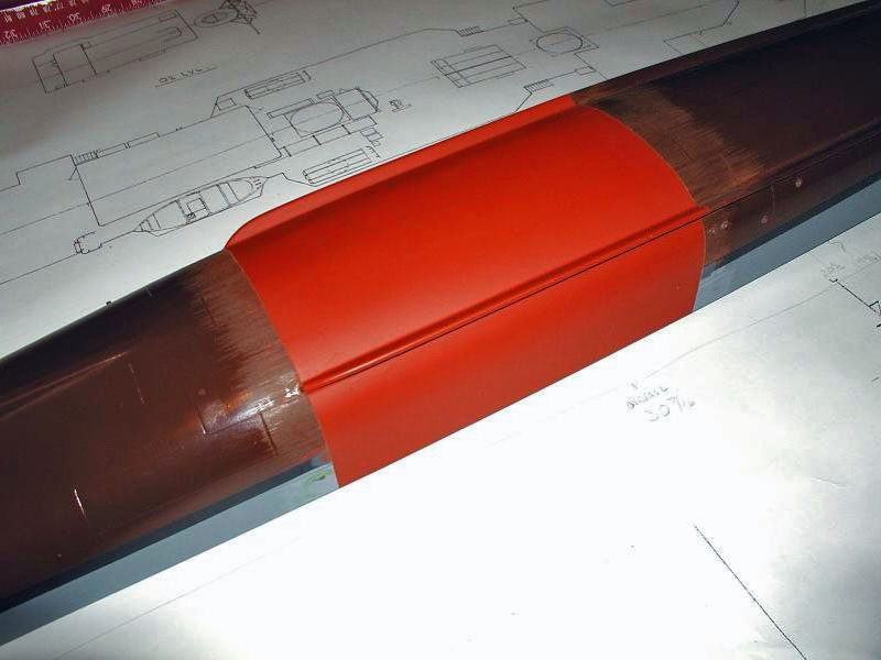
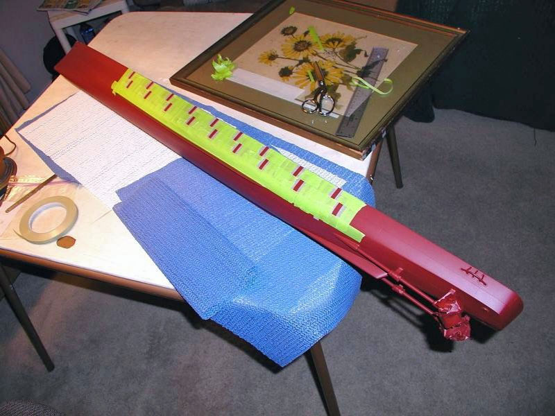
Before priming the newly-glassed areas, the fibre-glass is cleaned (as above) and scuff-sanded with fine sand paper on a sanding block to get things smoothed up and break the hard glaze of the epoxy. The primer may not stick to it well otherwise. After masking, a general overall few coats of primer were applied along with Green Stuff to smooth out the dings and dents. Two or more coats were applied to bring the new area's paint to the level of the old paint on the "still-painted" areas of the old hull. Then, alternating strips of masking tape were used to allow build-up of the primer in order to restore the simulated the hull plating which existed on the model before the conversion. I used a very fine grade of Scotch-Brite once the primer dried to scuff it up a bit before painting the color coats.
The USS Orleck is an operating model and is intended to sail seas of duck-green water, literally! For this project my airbrush tolerance level was at an all time low (needed cleaning from the last job). So I used rattle-can paints. They worked fine. However, make sure you get the can from the middle of the row at the store. The can in front may be solidified in the bottom of the can. Stock rotation, you know.
Dupli-Color and Krylon Automotive Acrylic Enamels were used for the color coats because of their hardness and resistance to chemicals and abrasion. They are inexpensive automotive paints and come in a variety of colors, and are readily available at your local do-it-yourself auto store. Although they fill the bill on all counts, there are many fine brands of modeling paints that can fill the bill on equal footing!
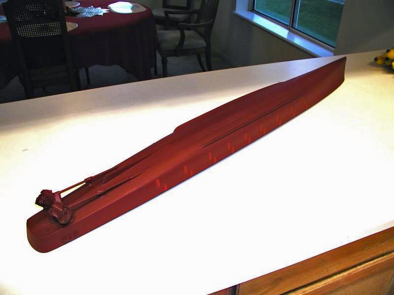
Shake the cans well and test the paint before using!!! I didn't! The Victory Red that I used for the anti-fouling paint below the water line was old paint and worked, just. I had much trouble making it flow out. Yep, bright red was intentional for the bottom in deference to those Revell Forest-Sherman and John-Paul Jones destroyer plastic model days. Pond sailors, all. Hey this is a hobby!
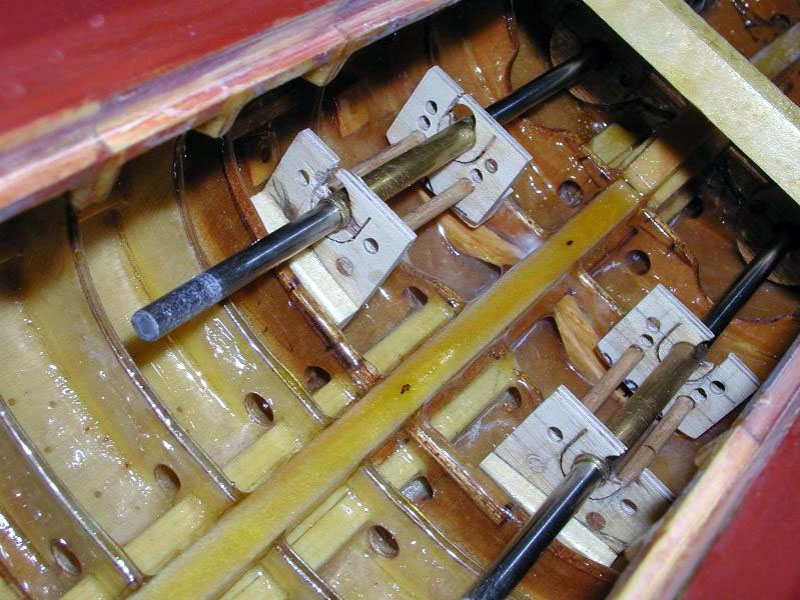
The motor mounts end plates were fabricated by locating and cutting the holes in 1/8th inch ply for the cooling holes, motor screw holes, water drainage, and a hole for a piece of brass tubing in the center of the motor-mount to fit the motors bearing-areas. The hole for the motor end bearings was partially cut after drilling the hole for the shaft alignment tube, using a "J" cut (see photo for method). The end plates were then assembled onto small dowels using super glue, which held the end plates far enough apart so that the motor would fit in between the plates after they were installed in the hull (allow for heat expansion of the motor as it warms up during running. 1/32nd to 1/16th ought to do.
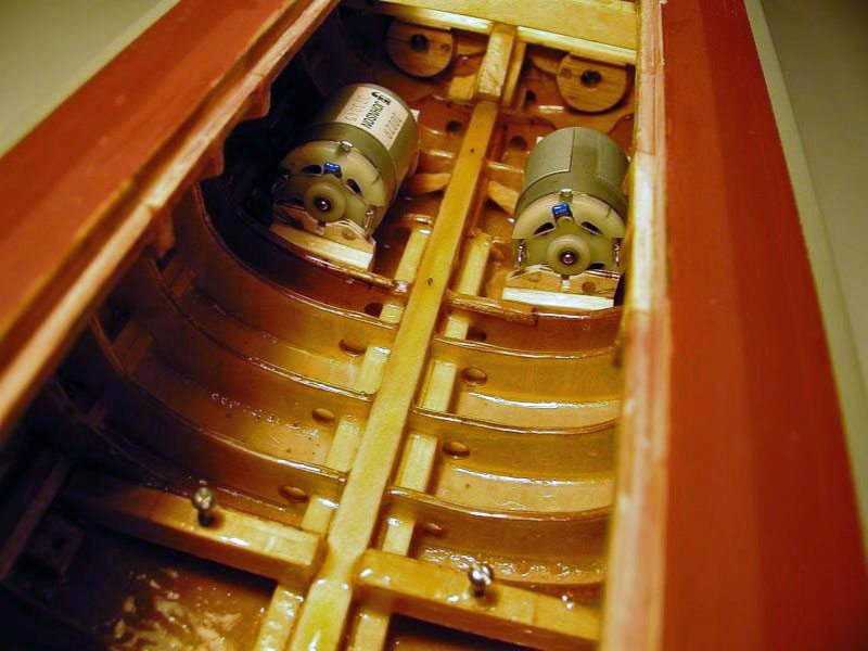
The end plate outside spacing happened to be less than the space between the frames on my model; so oversize shim-stock was glued onto the outside bottom of the end plates to take up the gaps. The shims were carefully shaped and angled with a small-block plane until they fit between the frames with a small gap left over for epoxy. The mount assemblies were then located into the hull between the motor area frames and the propeller shafts inserted through them, bringing the mounts right into line with the shafts (and ensuring that the motor shafts would line up with the prop shafts when they are installed). 5-minute epoxy was used to bond the mounts to the frames. The disposable area of the mounts that supported the alignment tubes was then cut through the remaining part of the "J" cut and removed along with the tubes (into the brass-scrap box of course). Long-cure epoxy was used to coat the mounts and adjoining frame areas for waterproofing after the tubes were removed and the edges sanded to remove burrs. The motors were temporarily installed to check their fit for final alignment later.
The radio and battery trays are simply 1/8th inch ply sheets cut to fit their respective areas, low in the hull for the battery tray. Once the exact locations for the equipments are mapped out, large access holes are cut through them to allow access to the bilges (very inside bottom of the hull) for water removal after sailing should some come aboard.
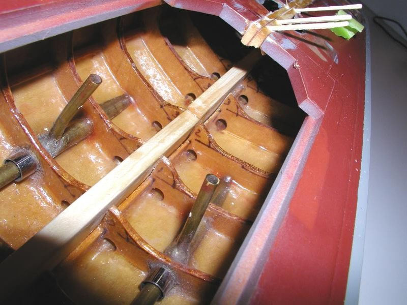
In the past this model in its Fletcher-form had been a very "dry" sailor due to the use of 'stuffing tubes' (simple brass tubing with a short piece of smaller diameter tubing that serves as a seal and shaft bearing telescoped into each end of the main shaft tube). The inside diameter of the telescoped-bearing tubing is chosen so that it fits the propeller or rudder shafting diameter. The resulting space between the main tube and the shaft is filled with Vaseline and works very well at keeping the water out. The filler-pipes for the props and rudders stuffing tubes are long enough to extend above the water line to help in keeping water out. Common English shafting diameters for 1/96th scale warships are �, 3/16th, and 1/8 of an inch. I use precision-ground stainless-steel, obtained from William BERG & Company. It is straight within 0.0003 thousandth, will not rust, and comes in a variety of lengths. BERG also sells gears, universal joints, couplings, bearings, belts, cogs, and other goodies that conveniently fit their shafting.
Above the waterline, the deckhouses are built to have a close fit to the deck and water dams are installed that extended about 3/4th of an inch above the access holes in the deck (and completely surround the access holes in the deck). The deckhouses have a small gap between their insides and where they fit over the dams. This allows for water the may enter to have a space to fill before it runs out again, preventing the water from flowing over the dam to the inside of the hull. These are things that I learned from reading Scale Ship Modeler Magazine years ago. The Gearing conversion project uses the same techniques.
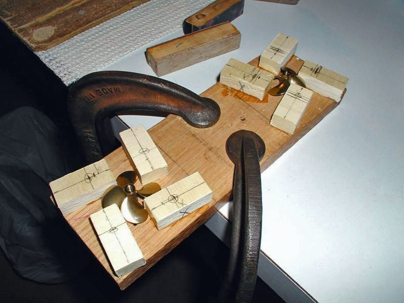

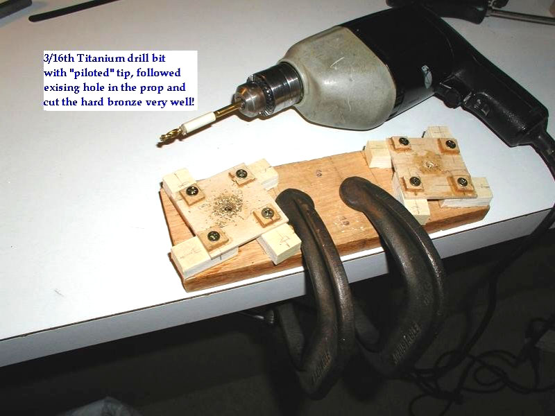
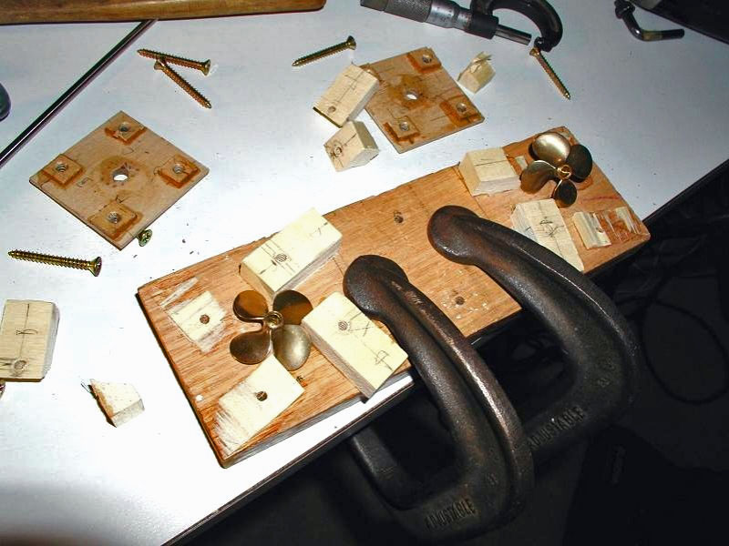
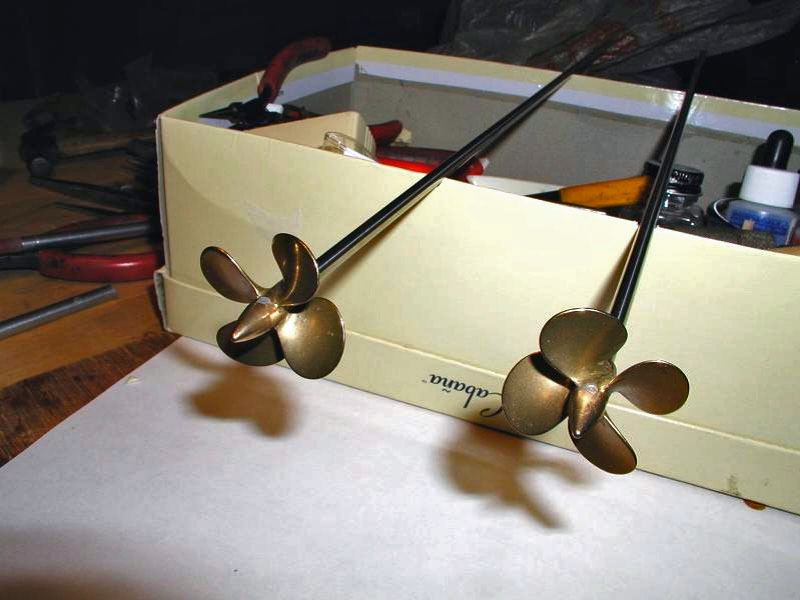
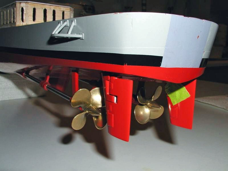
The propellers being purchased from a supplier in the UK were hard bronze had 4mm tapped holes in the propellers for the shafts. All the existing DD hardware was set up for 3/16th inch shafting. Bronze being hard to drill took some effort to get the job done. I built a fixture to completely captivate the props so they would not spin and not break off a blade when being drilled. The blocks were wedged tightly in-between the blades to keep them from rotating at all. I purchased a Titanium 3/16th inch drill bit that had a 'pilot-tip' on the end that, amazingly enough, was about 4mm. The hole-depth was marked on the bit with a bit of masking tape to act as a depth-stop indicator. I used a hand drill to do the job (a drill press would have been much better). Once the drilling started it took only a little pressure to drill the holes using medium speed on the drill. The bronze being very hard came out in chips rather than spiral shavings. The titanium bit cut the bronze like butter!
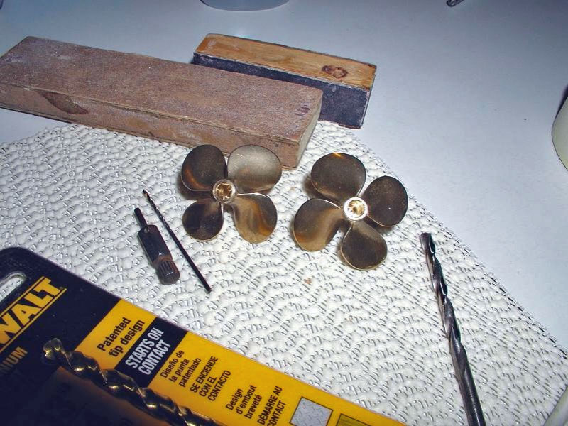
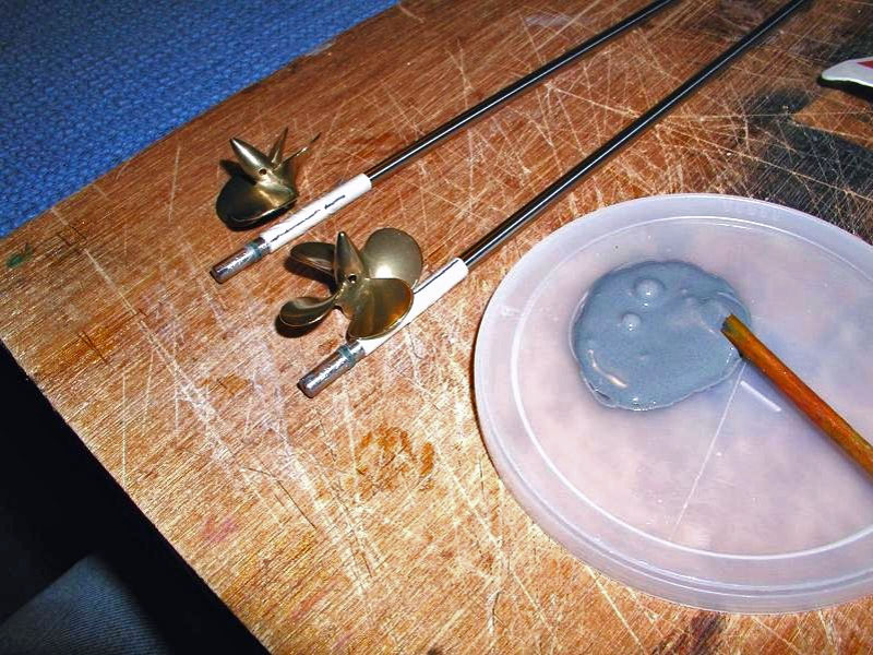
After removing them from the fixture a small hole was drilled in the 'dunce cap' at the bottom of the holes in the props to act as a vent to allow air to escape when the props were epoxied to the shafts. JB-Weld structural epoxy was used to bond them to the shafts and they were checked periodically while curing to make sure that they stayed fully on the shafts and remained wobble-free.
Having waited quite a long time for the props I did not want them coming loose, ever! I don't want to-drop-prop to the bottom of the duck-pond because of slamming the power into reverse from full forward and having it spin it self loose! Hence the JB-Weld. If needs be in the future I will cut the shafts flush with the props and re-drill the holes in the props with the Titanium bit. The math is simple. The shafts cost about $3.00 each, the props cost about ten-times that price, each.
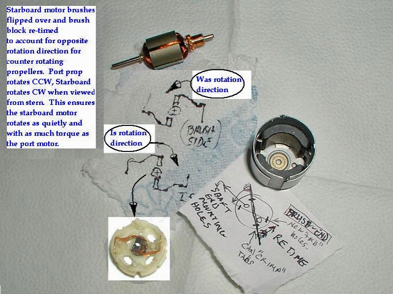
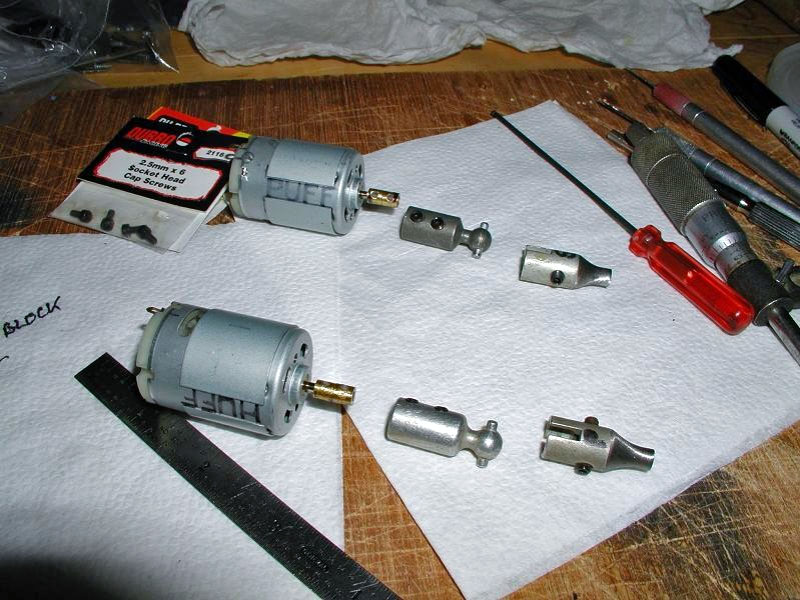
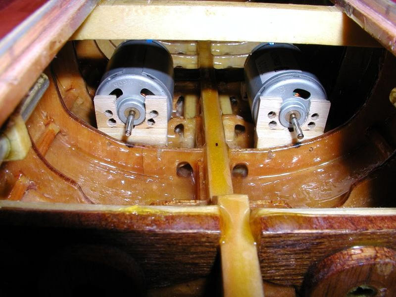
The motors that I bought for the ship were 'timed' to rotate most efficiently in one direction, that is the brushes are positioned slightly advanced to the normal direction of rotation. That, and the fact that the brushes 'wrap' around the commutator in the direction of normal rotation, gives the motors better torque, efficiency, and increased RPM in one direction. The reverse direction has less. Lastly, the motors are quieter in the normal rotating-direction. Most permanent magnet DC motors are 'handed' in this fashion. In some cases opposite rotational-direction motors can be ordered from a supplier (usually the 'dash 1' variety, too easy!!!) but mine were surplus (brand new) and are suitable for scale model ships because of their low operating RPM and high torque, so I decided to modify one to rotate efficiently in the opposite direction.
Warning, Warning, Will Robinson! Advanced skills needed here! Don't attempt this if you cannot afford to throw the motor away!
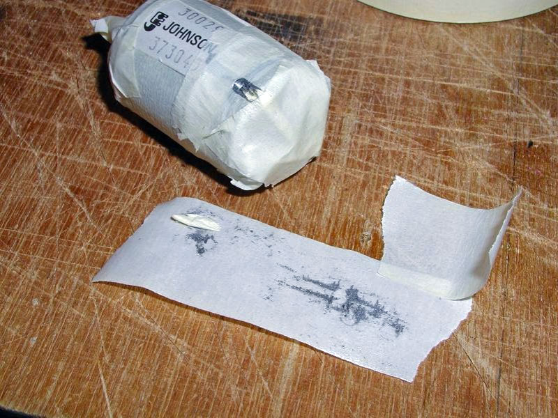
To do this I flipped the brushes over in the brush-block and retimed the brush-block in relation to the magnets to get 'advance' in the other direction. The accompanying pictures give an idea of what was done. Suffice it to say that it was difficult to do. The tabs on the can would not un-bend so I had to grind them most of the way off until they would. I used masking tape to keep the shavings and filings from sticking to the can and magnets. Tape can also be used to 'pick-up' any that do. The brush-springs and wire-posts had to be disassembled by drilling-out the three 0.010 spot-welds in each one. They were then soldered back together after the brush springs had been flipped on the wire-posts. It worked out well. The modified motor does run identically in all aspects to the other one, except in the desired opposite direction.
Once the motor was modified, both were installed into their mounts, making sure that they turned the right direction for the propeller they were turning. When viewed from astern the Gearing DD's props used CCW rotation on the port prop and CW rotation on the starboard prop. The motors were 'bedded' with 5-minute epoxy into their respective mounts one at a time after connecting it to its shaft. Each motor was coated on the ends with a thin coat of Vaseline to keep the 5-minute epoxy from sticking to it. Each motor was then run with a 9v battery and the motor was moved around up-down, left-right until maximum RPM was reached, and then held there until the epoxy cured. Peaking-out the RPM in this manner shows where the minimum amount of running friction occurs and will help get the most running time out of a battery charge. Once the epoxy fully cured the mounting screws were installed, again running the motors to make sure that they were not pulled out of alignment by tightening the screws.


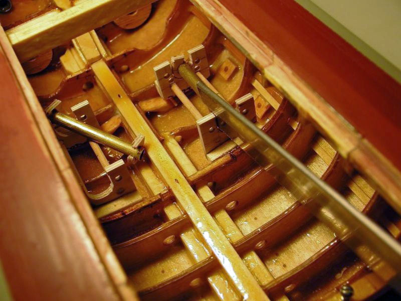
The rudders are interconnected to each other as they are on the real ship. Also each one is connected to the rudder servo by Golden Rod to ensure that they both rotate the same amount in both directions, one on each side of the servo wheel. Unless the flexible control rod is anchored down at regular intervals to the hull a rudder may rotate more in the servo 'Pull' direction than it does in the 'Push' direction. The problem solved by using the method shown in the photos. I normally mount the radio receiver and servos near the bow to separate them from the motors and ESCs, which generate broadband RF noise because of brush arching while running. The filter caps on the motors help to filter out the RF noise that can interfere with the radio control signal. The extra distance between them motors and receiver helps too for much the same reason, hence the need for long rudder control-rod lengths.
![]()

Back to Warship Models Underway
This page maintained by Kurt Greiner. Email me here.
This page viewed 108
Version 1.1
Last update 12/09