


Click on any image that has a border to enlarge. -
To see more of John Hayne's models, click here.
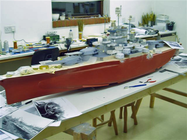
John started from scratch, building the plug for a fiberglass molding.
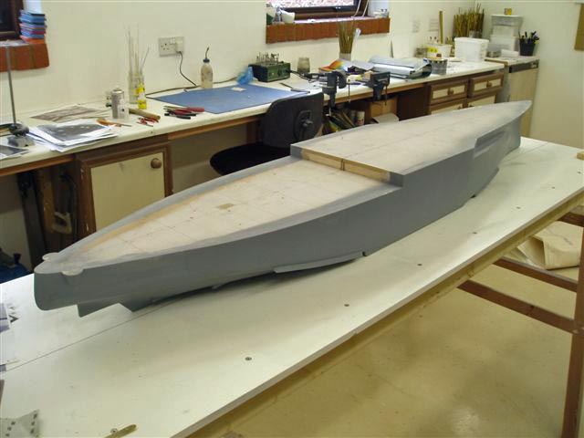
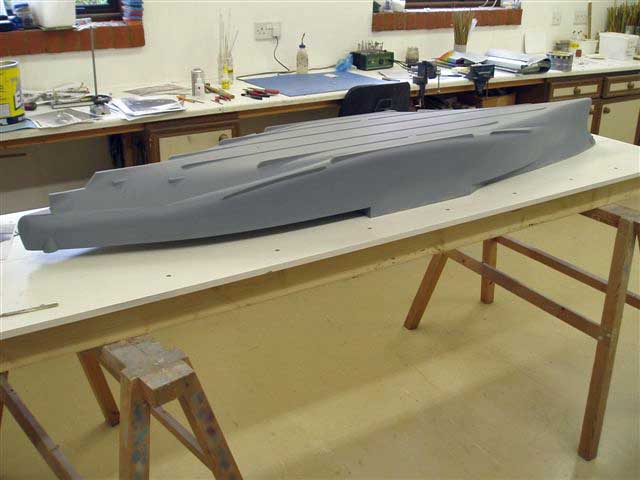
The hull being quite light John had to stiffen it up with 9mm ply in strips to follow the contours. The hull was then braced to get the correct 360mm width. more bracing was then added and shaped to give the camber [ 4mm rise] with the aid of a template.
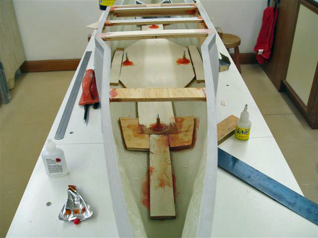
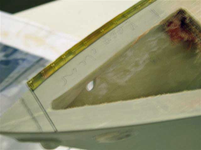
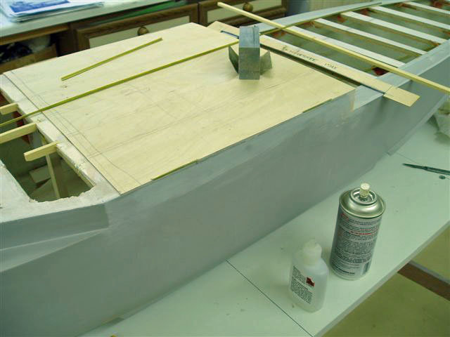
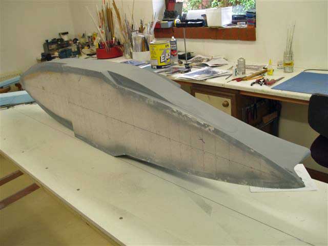
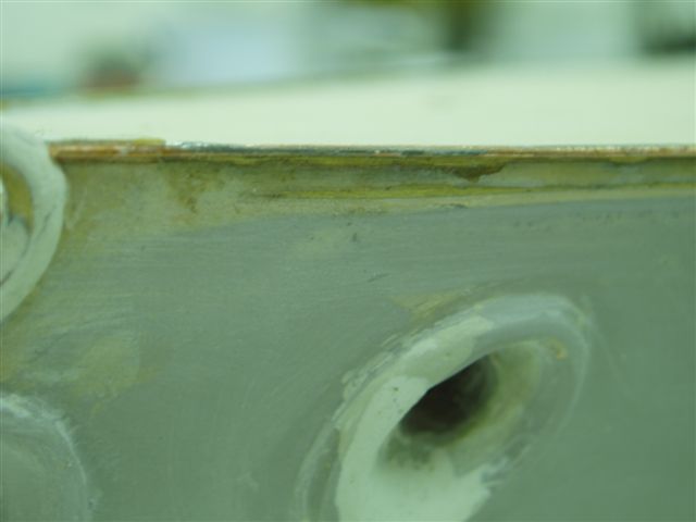
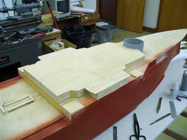
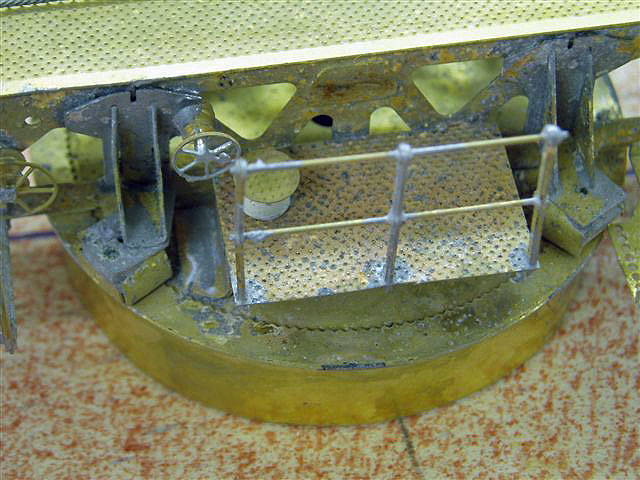
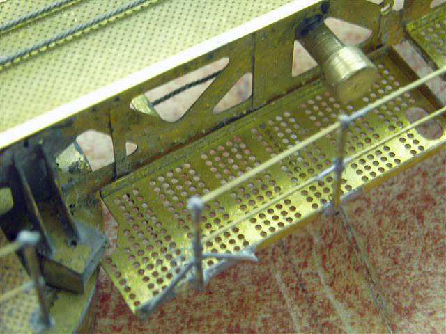
The center portion of the hull was then covered with 1.5mm ply. John fitted the forward bow section with contoured cross beams but before he fit the sub deck the deck edge had to be fitted with Special Shapes A4 angle iron (A.I.), heat treated to get the bow flair that follows the hull line. To fix this he pre-drilled with a 0.5mm drill holes in the A.I. about 10-15mm apart . The A.I was then offered up to the hull and drilled into the grp. It was taken off again and hull and A.I. cleaned up and re-fixed with brass pins . These are then soldered and cleaned off and the deck will then be fitted which traps the A.I.Later I will solder around the top edge of this angle a wire , as on the real ship The sub deck is cut out on the underside edge to a depth of 0.75mm to allow for the A.I. thickness.
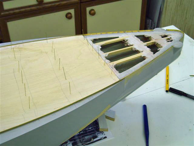
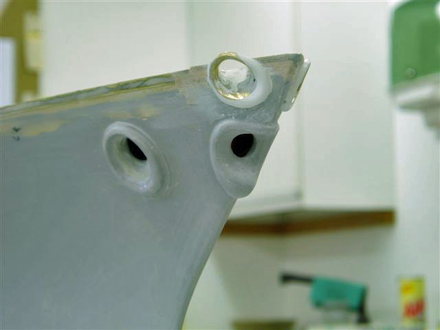
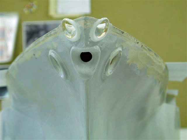

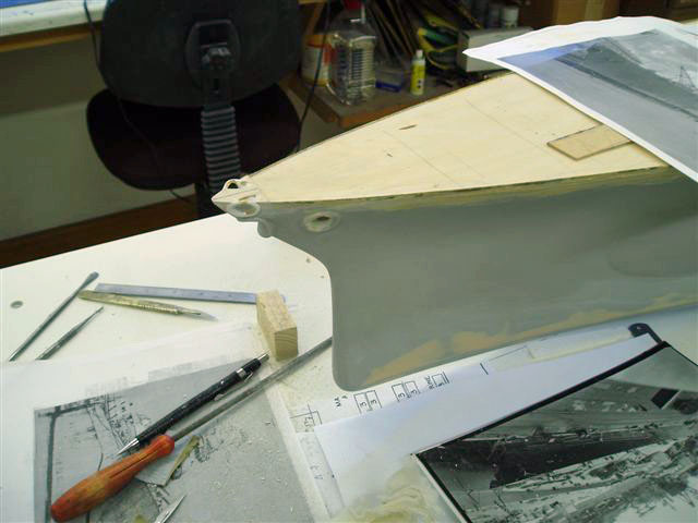
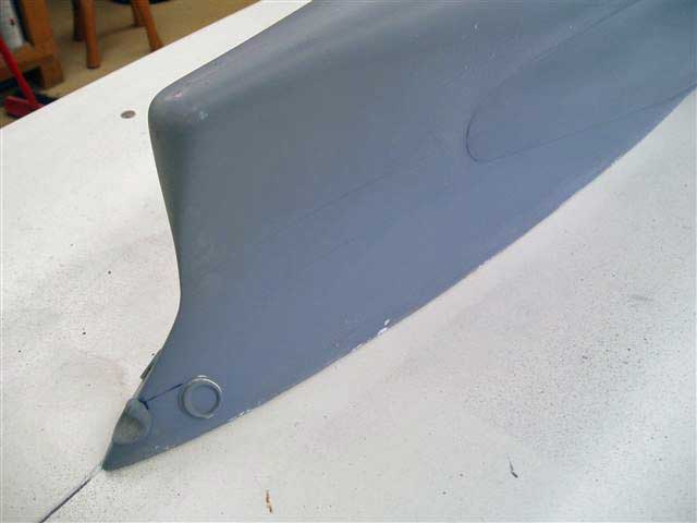
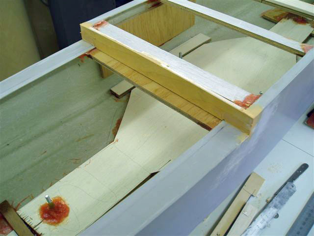
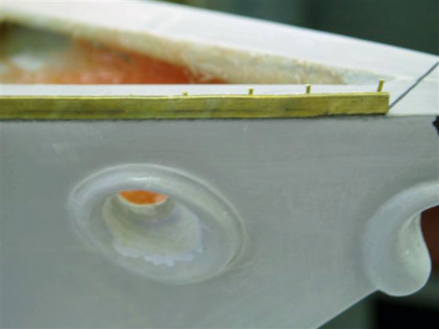
The subdeck is nearly complete at this point, with the end of the stern left open to fiberglass the skegs. The bullnose is made with a combination of Milliput and turned brass rings, as this is a difficult area to get right.
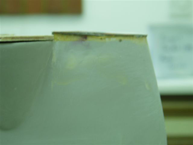
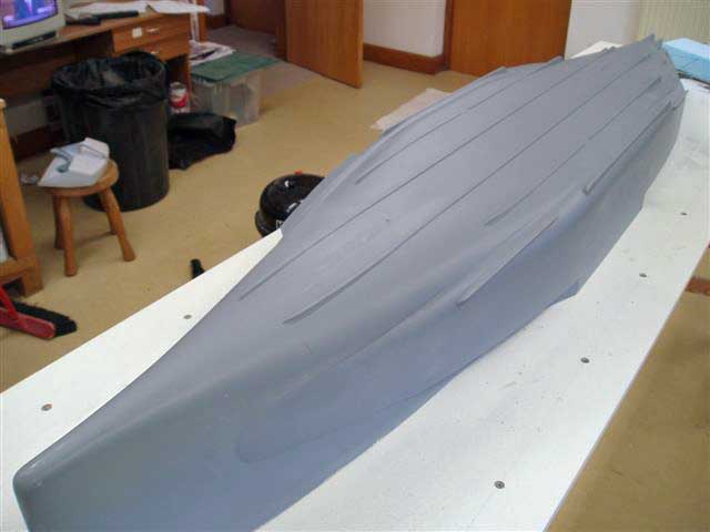
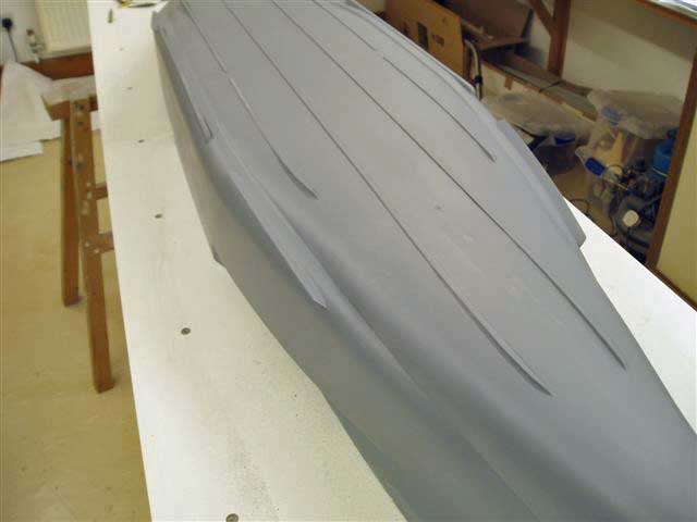
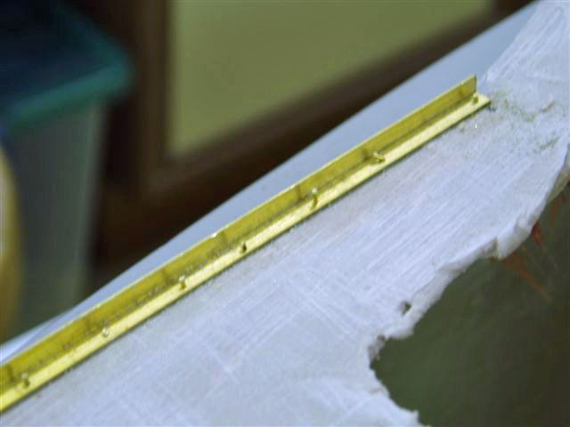
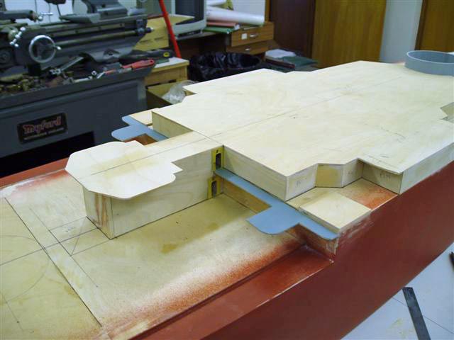
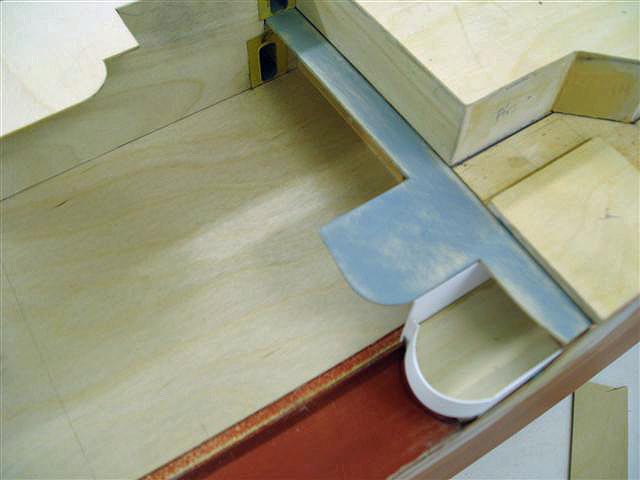
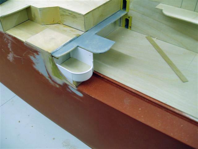
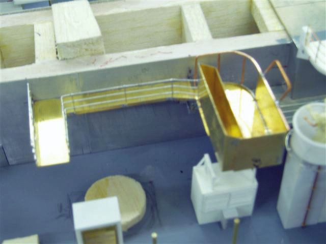
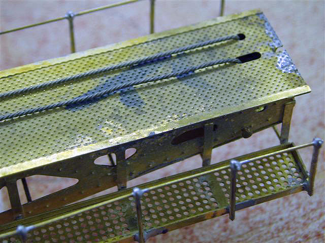
The stern drops as shown . John is soldering onto the A4 angle on the outboard / top edge a 22g copper wire . The lined area will be covered by a 1mm lined deck . This deck is fitted at the last stage when finally assembling the model after building and painting
This is the starboard side wire being soldered on, adjacent to the rear 20mm tub
July 28, 2006
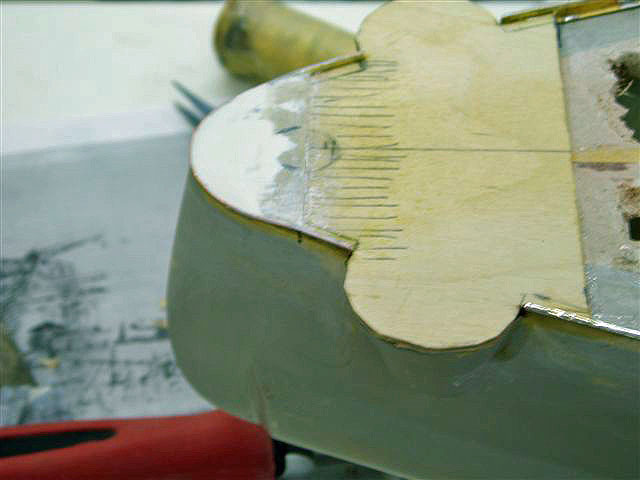
John has finished the soldering on of a wire to the top outside of the brass angle on the focastle deck edge.
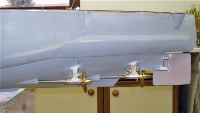
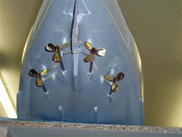
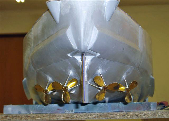
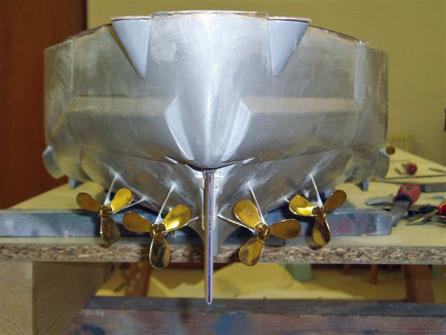
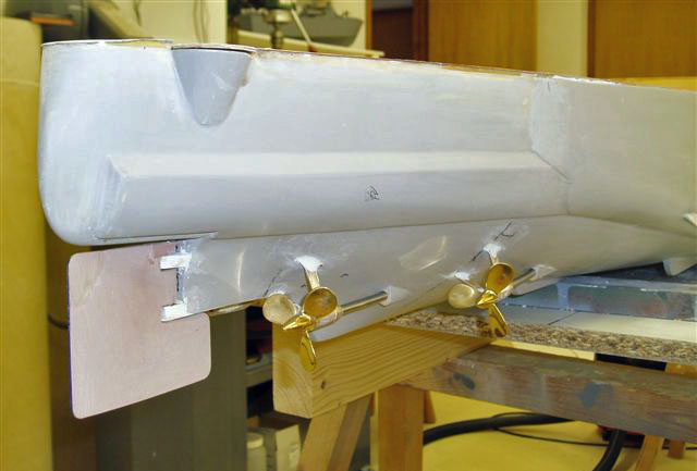
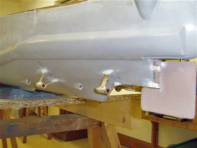
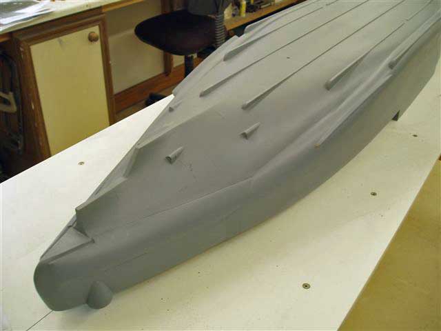
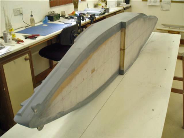
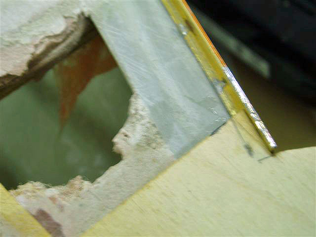
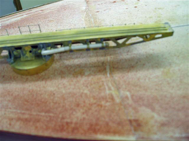
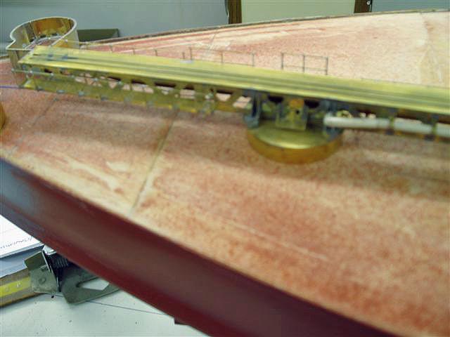
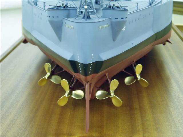
The prop skeg sleeves were turned up and the brass stays soft-soldered to them. Use was made of the product called " cold front" to prevent one stay being de-soldered while soldering the other. Slots were cut in the hull to accept the stays which were then glassfibered in, and care was taken to make sure the props were positioned as plan and were level with each other in the vertical plane. This was achieved with the hull right side up and an equal height piece of wood on which the lower prop blades were rested. After cleaning Milliput , a two part putty, was used to dress out the joints and get the right look. The rudder is carved out of ureal, a dense easily carved material. It sits when in position on two brass pins fixed in the hull square bosses which were fixed to the grp rudder post with turned pins.
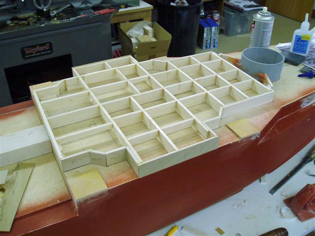

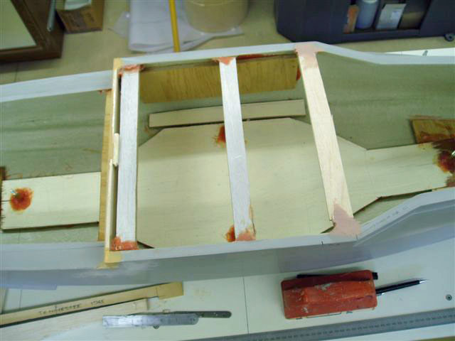
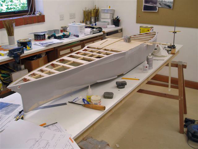
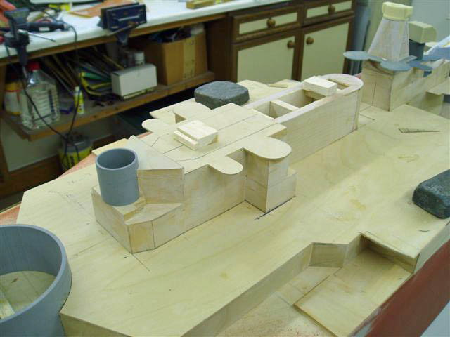
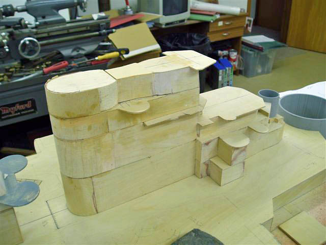
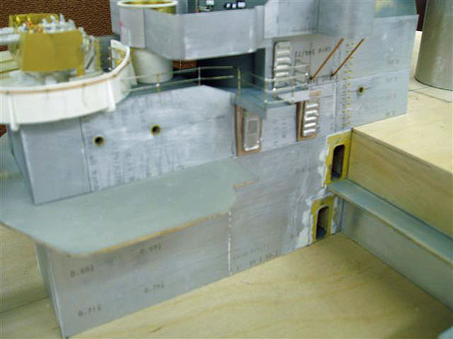
The 01 level has now been blocked out using an eggshell style of support in balsa [ a quick method and even quicker using thin instant glue ] with a plating of 1mm ply over and a 1.5mm deck added to include the overhangs.This area has to be correct in all planes, camber and vertical. The rear section has been made separately for easier detailing and finishing. All of John's models are finished in sections to detail and paint , in essence he creates a kit to assemble. Sections are added and come off the model regularly so somedays it looks almost complete and other days as if it was just started. More sections will now be added and when complete all will be covered with 0.5 thou old litho plate. This will blend in the brass PE access plates that are visible on the separate section.
August 12, 2006 Update
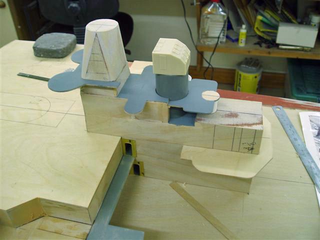
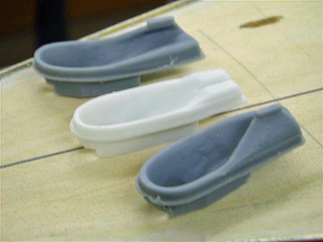
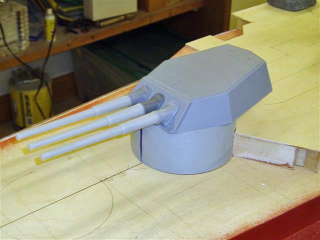
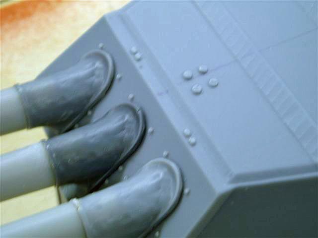
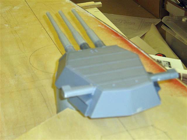
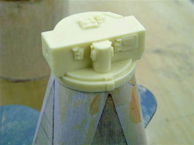
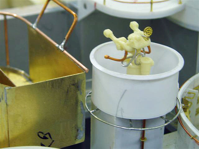
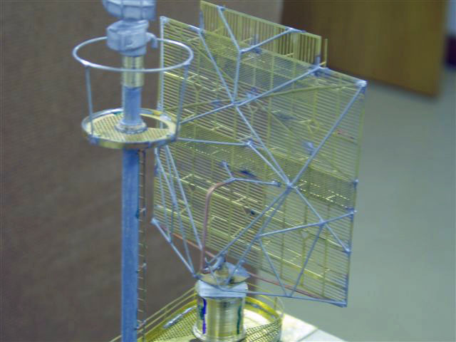
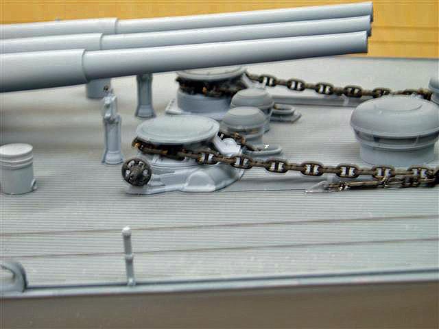
Some of the resin cast items are being delivered, and some detail work has commenced. The deck hawse lip set need to be sunk into the deck. John has test assembled one of the turrets, which turned out OK. Turret sets could be available to those interested. The superstructure has given him some problems due to discrepancies between the plans and photos. Mr. Cliffton Simmons has been of assistance here.The Mk 34 director is being moulded in resin in two parts , the main director and the rear rectangular piece that attaches to the multi-holed front plate . The two ends are included in the resin so that it sits squarely on the PE pyramid supports. The photo-etch is being put on the computer but is quite extensive and will take a while yet. Also PE'd will be the front plate and the aerials that sit into this. When working on a project like this you have to build the model sequence in your head before you start to ensure that what you need arrives on schedule and within the program of the people you depend on .

August 21, 2006 Update

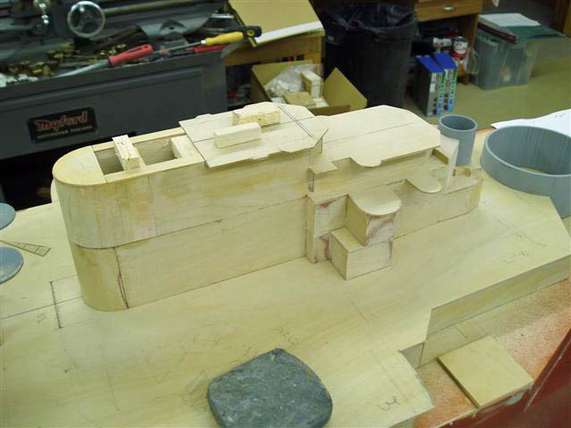

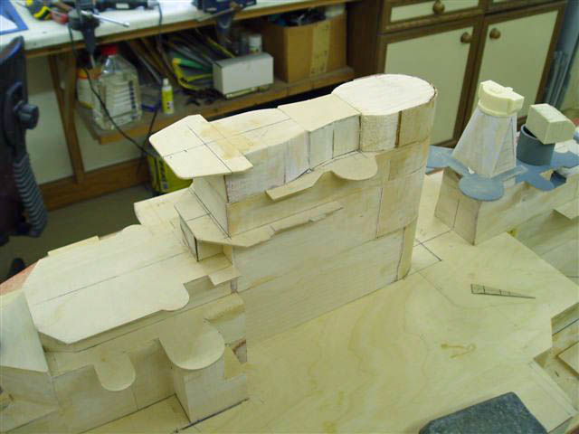

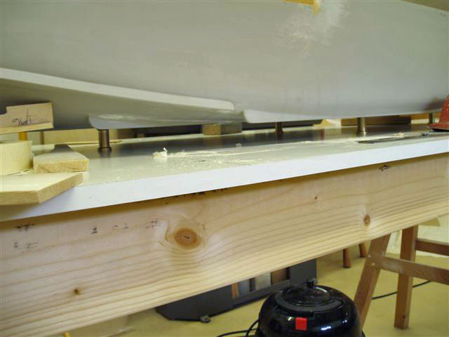
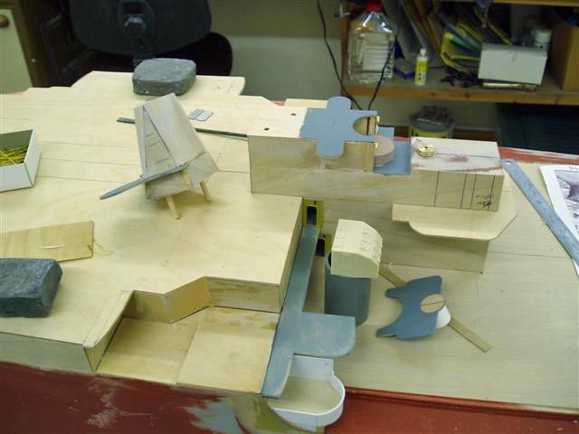
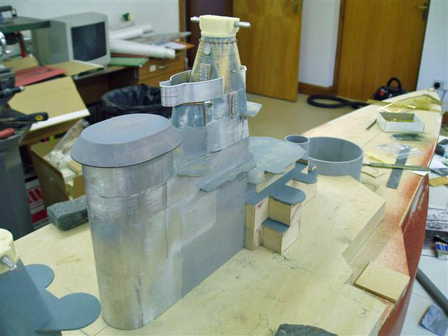
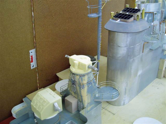
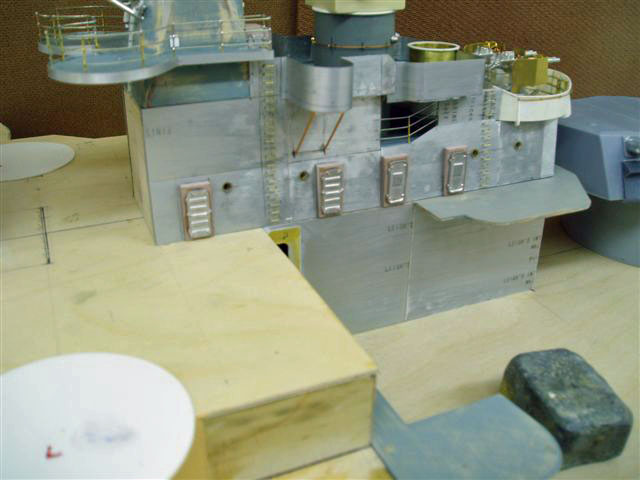
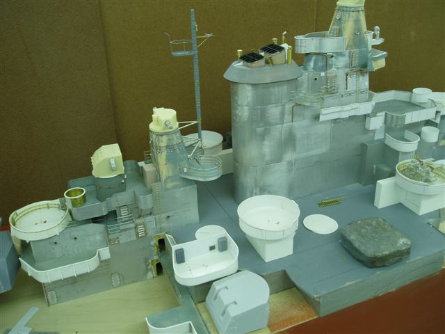
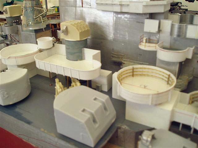
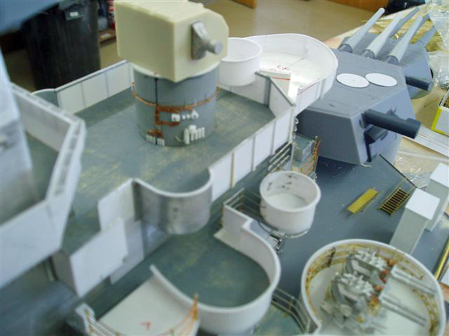
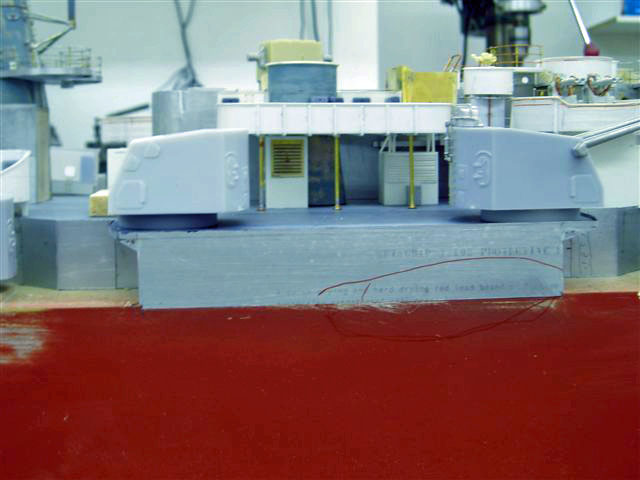
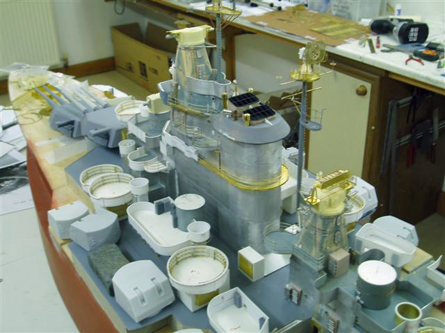
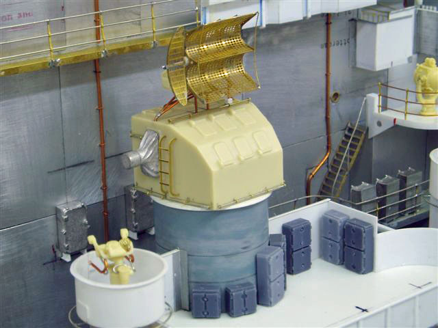
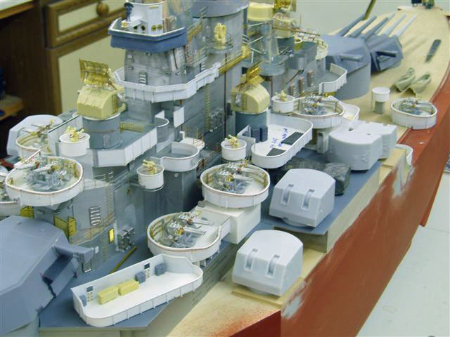
The main upperworks have been built in sections to facilitate finishing . Each section is located on the next so as the building continues the sections always locate in the exact same position. The Mk34 resin body is in postition awaiting the sights and photoetch. Once all the sections have been built and faced with 1mm ply , each section it will be covered in litho plate. This gives the metal look and means that all is required is to detail and spray. Incidently , the two weights in view have been left in their port and starbd positions to prevent the 01 deck lifting during the months of building. From past experience this does happen over time if the deck is not glued down , as in this case.
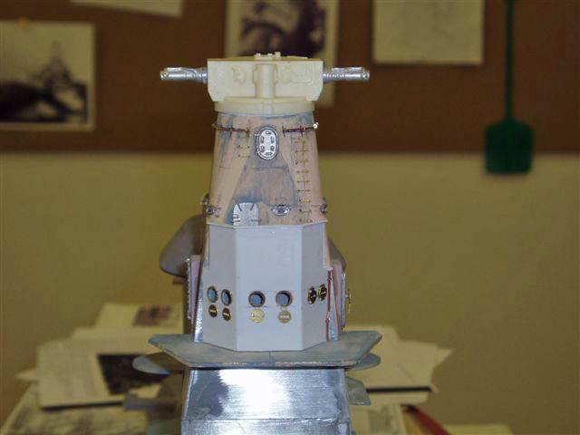
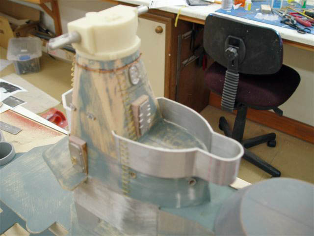
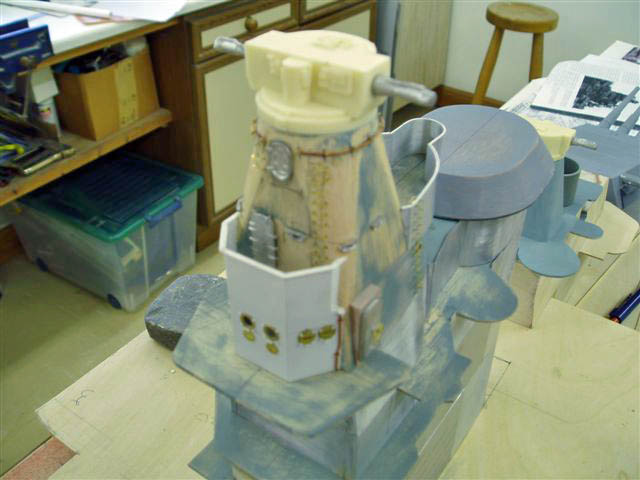
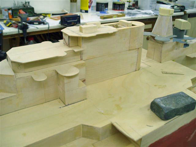
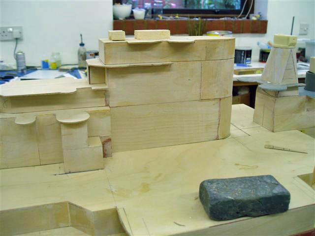
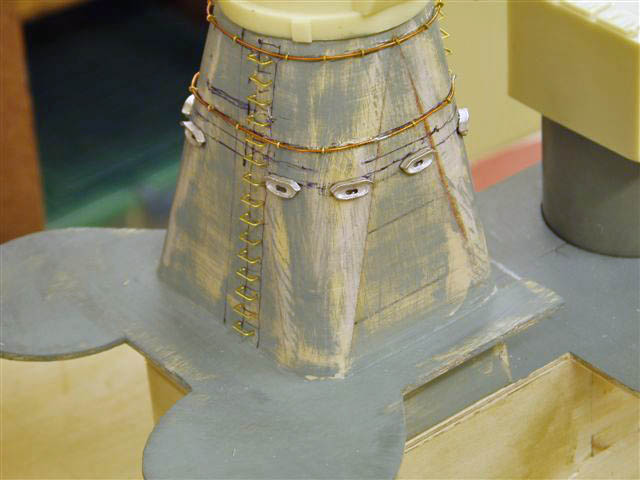
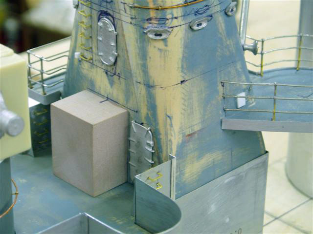
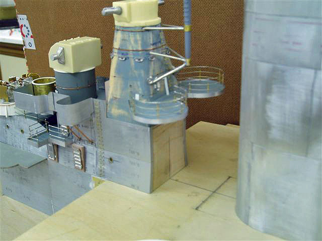
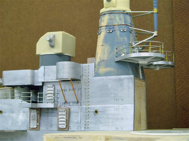
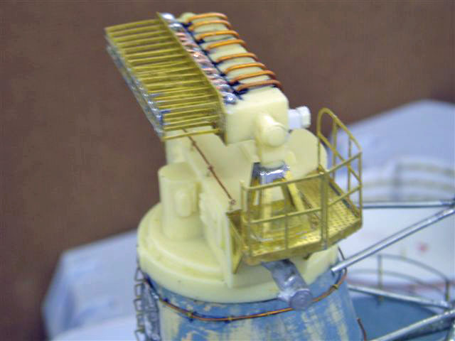
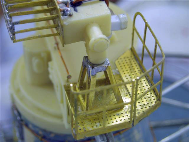
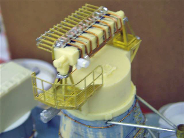
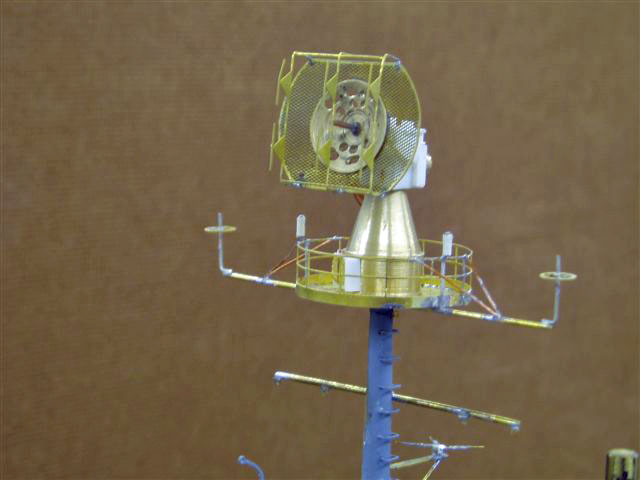
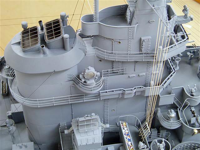
The forward director tower is 80% complete. Still waiting for the PE for the Mk34 directors.The funnel cap has been fixed in position, and all the plating with litho has been done, section by section to enable each level to be disassembled for detailing and painting. The armoured top has PE rungs and peepholes added.

Work continues on the funnel and other top areas, working down but still waiting for the PE which will have to be added much later. The PE crane for this ship, part number JRH 703, is in production and will be available in October 2006. This can be used in conjunction with the white metal base kit already available, number JRH 702.
September 28, 2006 update
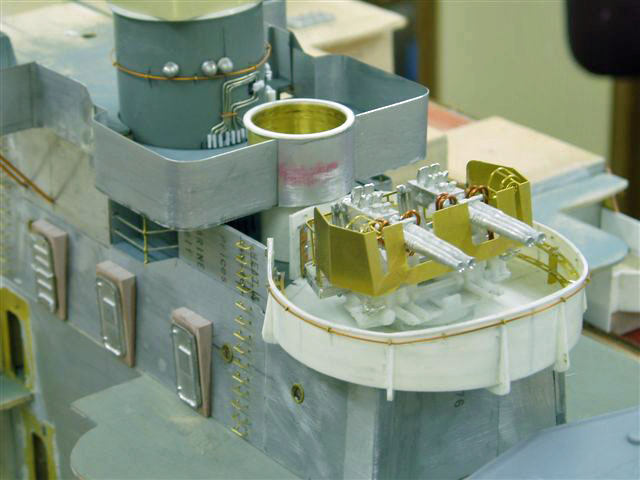
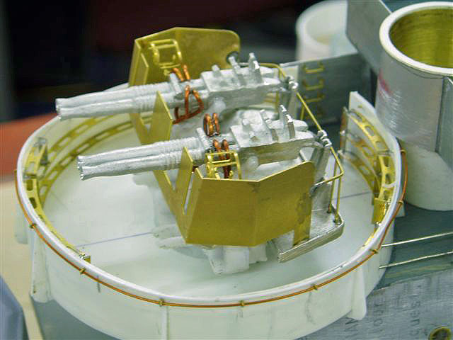
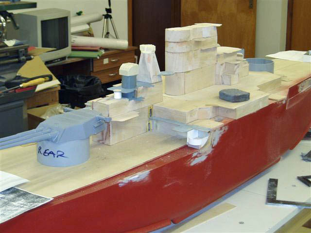
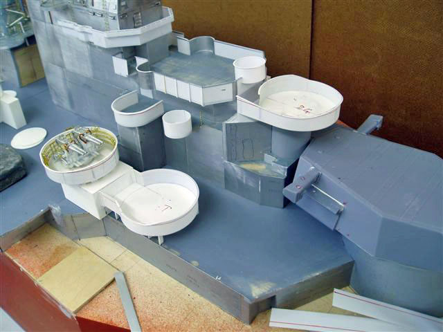
Concentrating lately on the rear upperworks. This is still awaiting the PE platforms and other detail. In the shots there is John's JRH 80 Quad bofor kit that is available, also the Mk37 director JRH 118 which is supplied with the PE Mk 12 radar which that is yet to be fitted. This rear upperworks is in three parts that disassemble, the armoured top, the main body and the platform carrying the Mk 51 director and tub
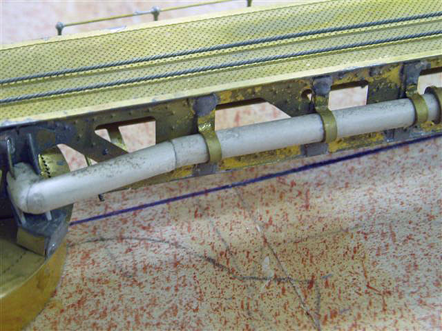
October 14, 2006 update - John writes:
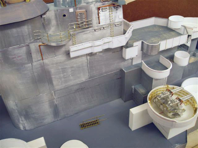

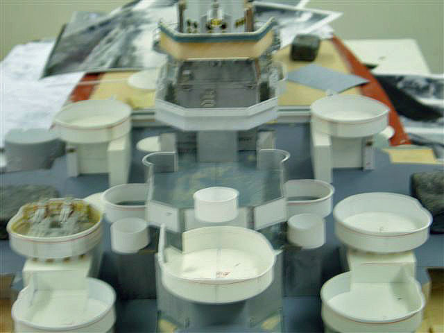

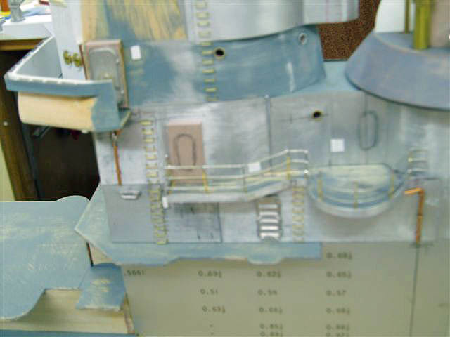
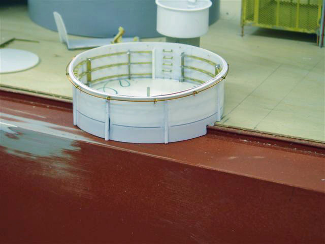
The bridge area has been under construction along with the hull outer edge 40mm tubs and their bases.Still awaiting the platforms PE sheet but can cope since there is still other work I can get on with.The plating in 5 thou litho aluminium sheet is now completed on the central structure, still to add rungs, doors etc. If I thought that there is a market for a fret of pe rungs that I produce at 4mm wide and 3.5mm wide I would maybe consider running them ? The crane pe has been returned but needed slightly altering so need to run new films and get a new sheet of brass, this is where it gets expensive.Have white-metaled the long refueling hoses which look ok but cannot be fitted at this stage since they will be blackish in colour and I do not try to pick out detail in colour, only spray off the model then fix - that way you get a decent result. The 40mm rings are taken off my JRH 662 tub fret along with the brackets which means I will have to dump the rest of the fret but is a cheaper way to go rather than create a new sheet of just rings with the artwork/film /brass sheet cost far outwaying the cost of discarding 662 pieces.
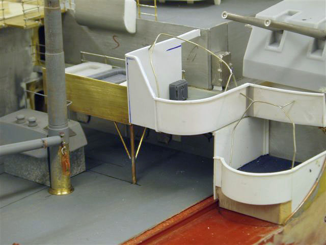
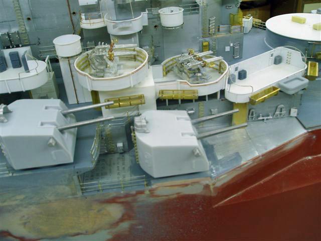
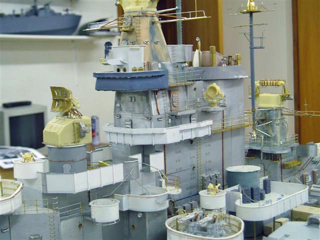
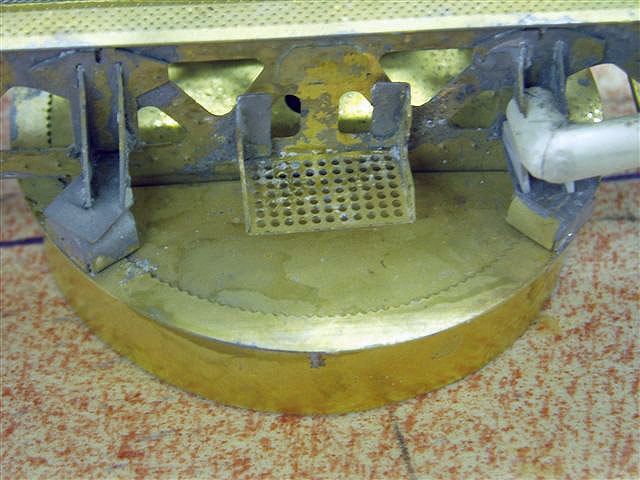
October 21, 2006 Update. John writes:
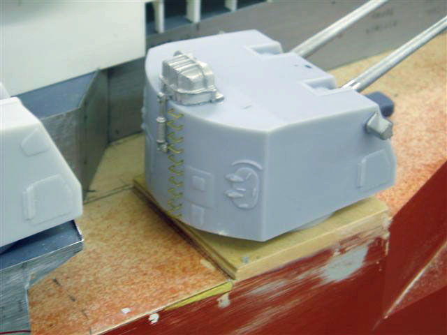

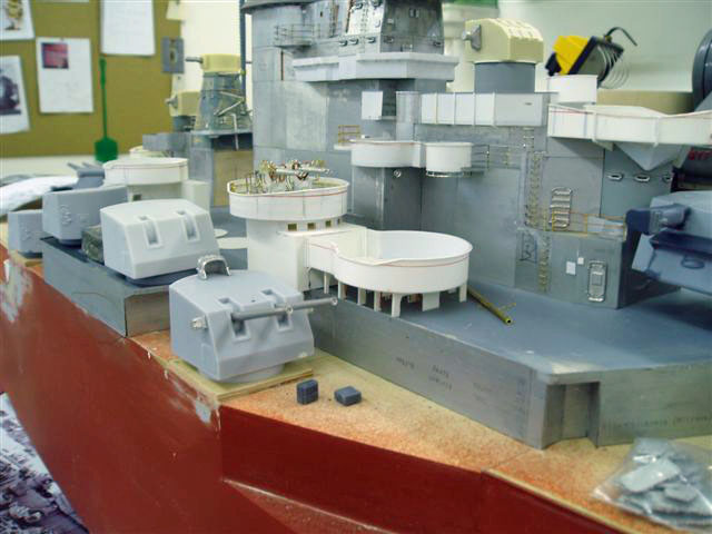
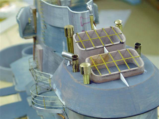
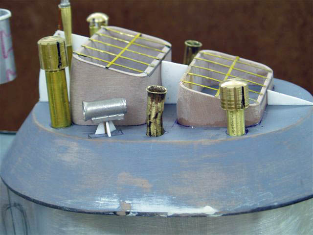
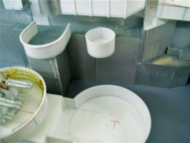
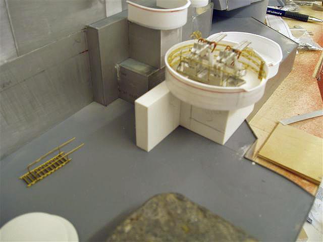
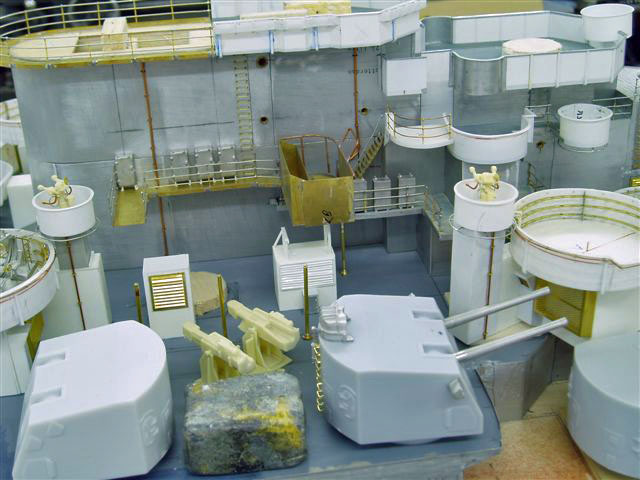
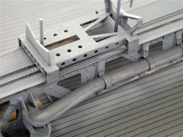
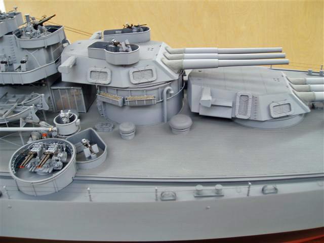
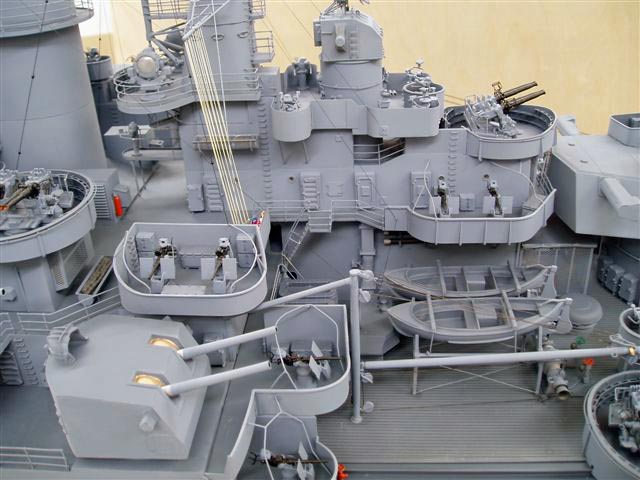
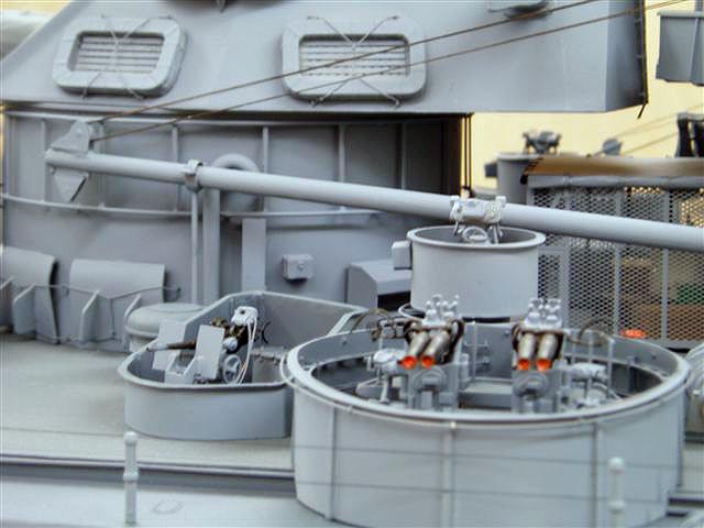
Here some progress has been made , the 5"/38 twin turrets which are my kits JRH 567 are being assembled. Sorting out the shell catcher beneath the 40mm tub adjacent to the bridge and detailing this area as well as the platform either side of the bridge that carries the searchlight , oerlikon and mk.51 sight
October 24, 2006 Update. John writes:
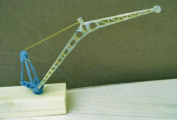
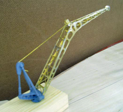
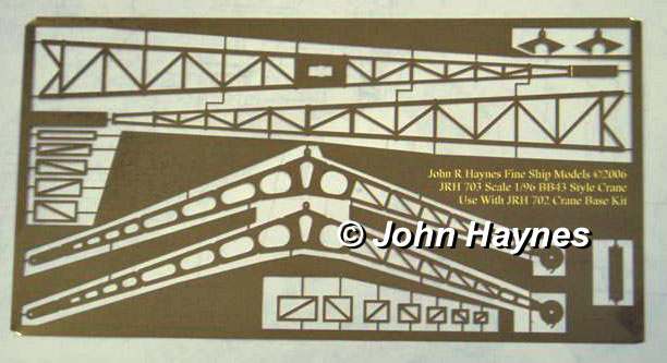
This is the BB43 PE cane JRH 703 at �8 now available. When buying the base JRH 702 [ �7] and 703 as a set , the 2 crane wheels are included, one at the top and one at midway point. The crane shown has a temp. wire connecting the PE to the base. The photetched fret is also shown.
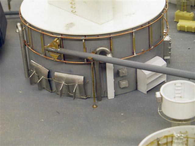
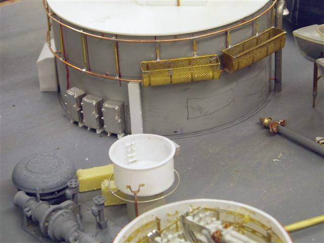
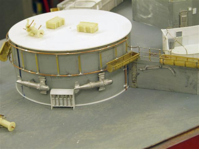
November 10, 2006 Update. John writes:
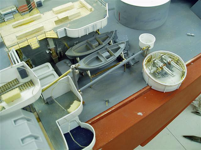
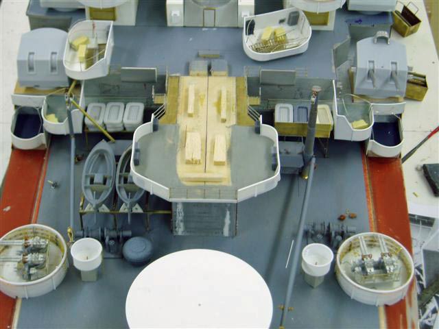
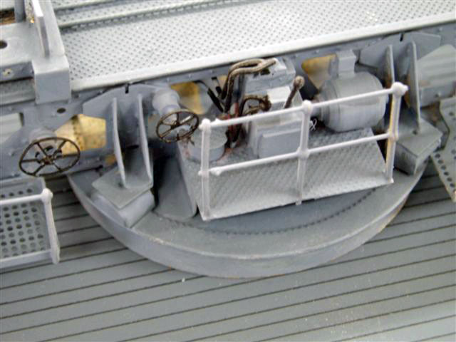
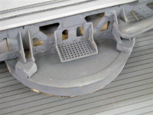
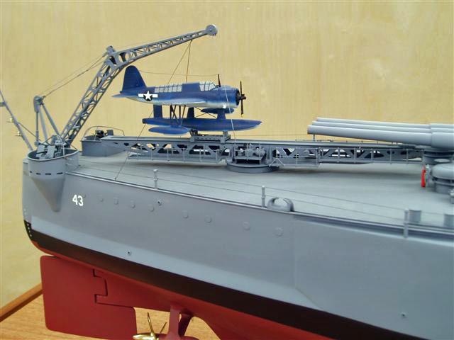
More progress photos of the centre section of this fine ship. PE platforms are on the way so should be able to finish some areas before too long. The catapult is on the computer for Photoetching, and this will compliment the BB catapult JRH631 I already sell.

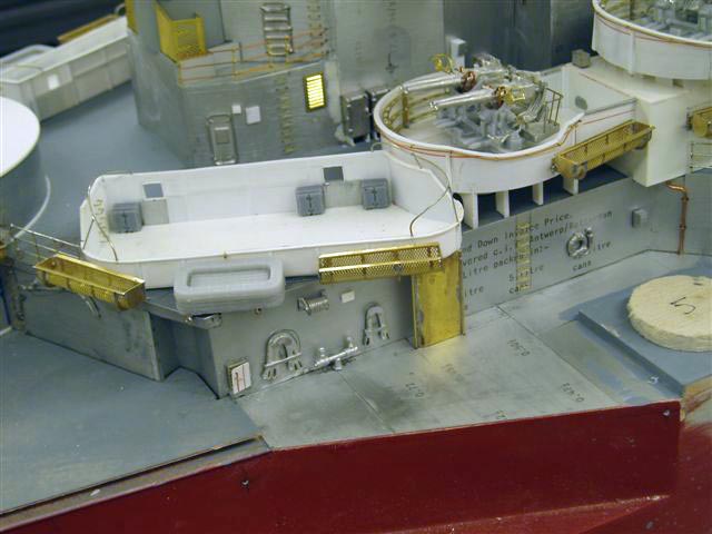
November 17, 2006 update. John writes:
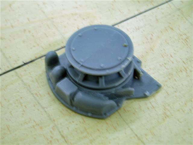
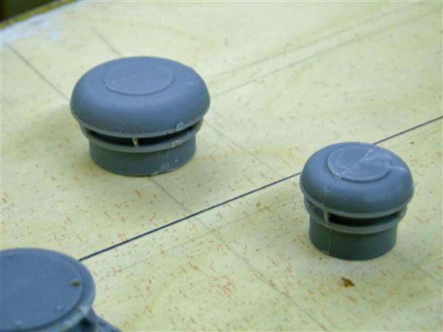
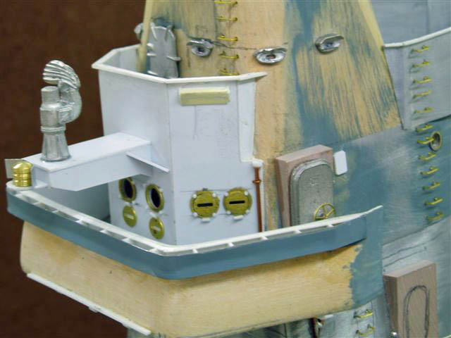
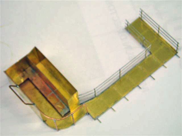
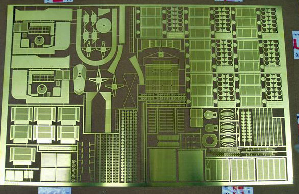
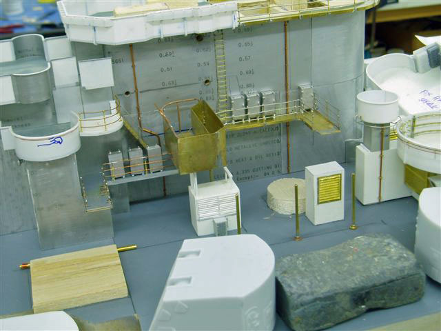
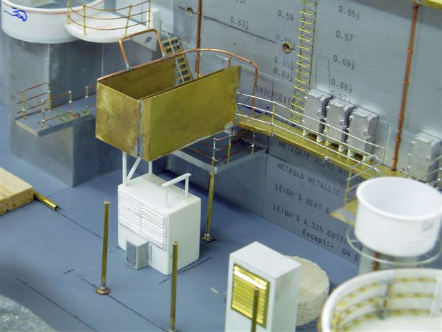
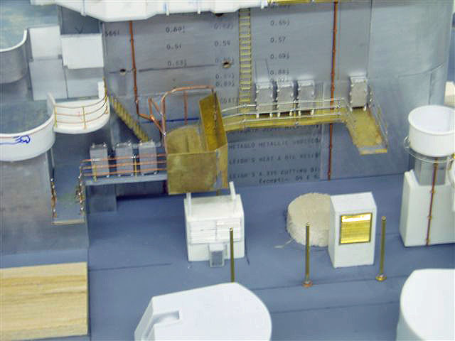
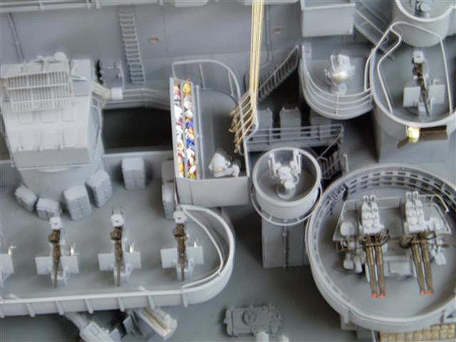
Now that the composite fret for this job has been returned progress on parts left unfinished can proceed. The brass platform amidships port and starbd containing the flag lockers [as opposed to the focastle break flagbags] has been soldered up . Brass pins were fitted into the main structure and the platform soldered on to them . The whole assembly was the removed and cleaned up. This platform will be treated as a seperate part and sprayed and fitted during the final construction stages.Also shown is one of the finished Mk51 directors and also the deck level vents under the large Oerlikon platform [ tray] with supports for the tray above. I have shown the composite Photoetched fret and highlighted the SK radar . This will be seperated and put on another fret and put into my range.


November 20,2006 update. John writes:
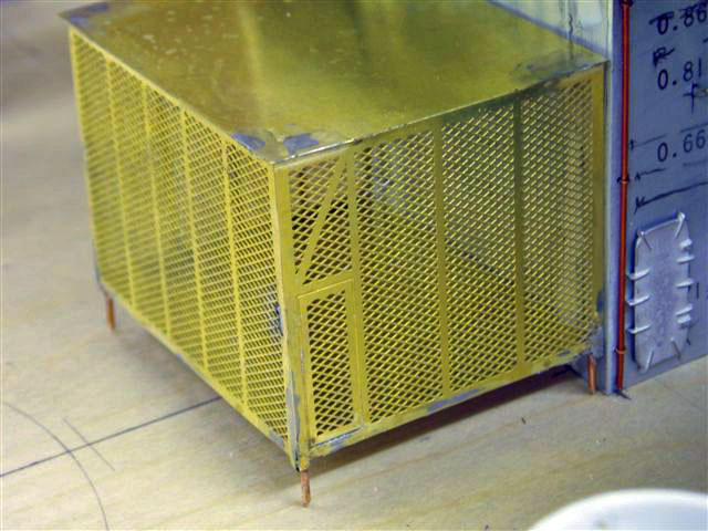
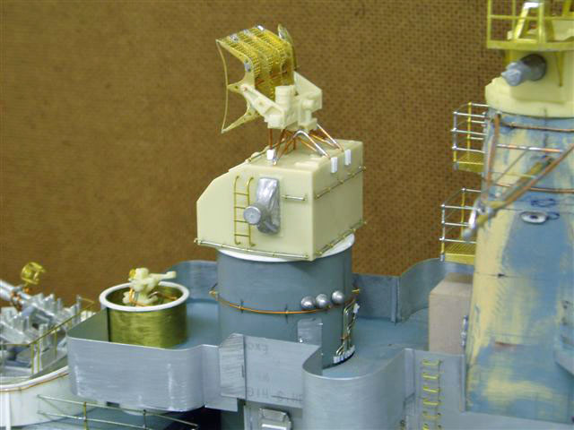
This shows the MK 34 director and the large vegetable locker , which is taken from my composite sheet . The second PE sheet has been done to correct all the mistakes on the first and to include the focastle tread plates. The SK aerial set is now being put on a seperate fret and to be part number JRH 706 and will available in a couple of weeks.

November 25,2006 update. John writes:
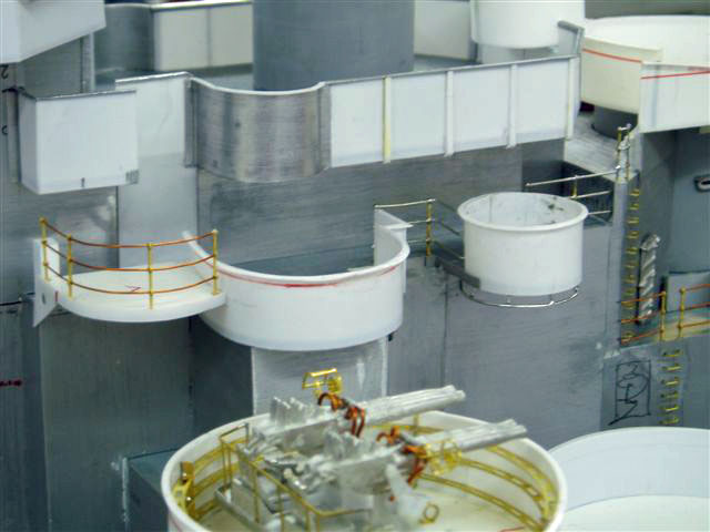
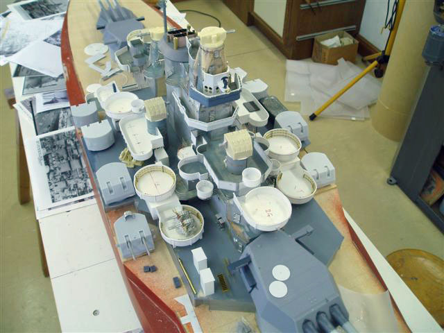
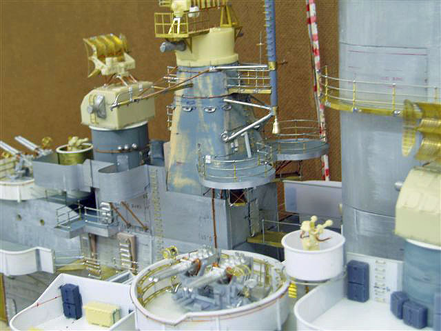
I am now fixing the various platforms in position and constructing the SK radar on the Photoetched platform together with the SP radar , a difficult subject to get right. The SG radar and PE platform is now fitted on the uppermost mast. The two quarterdeck 40mm tubs are constructed but are only push fit in position. Due to some failures on the Tennessee PE sheet 1 , I am now running sheet 2 with other items on this sheet also.


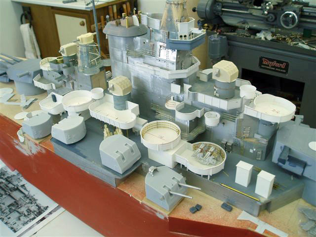
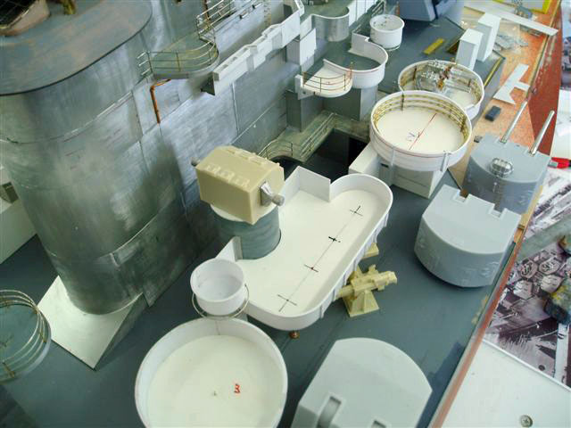
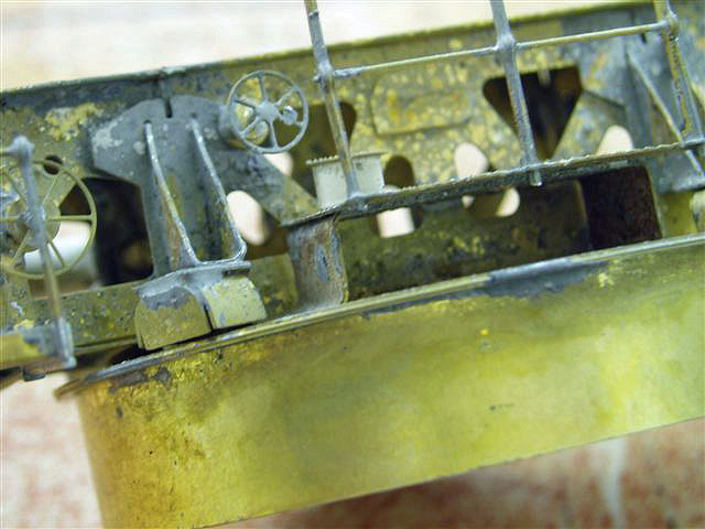
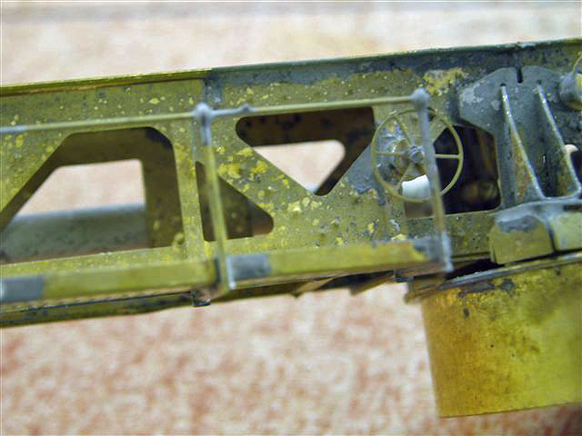
November 30,2006 update. John writes:
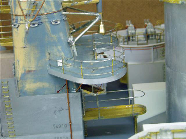
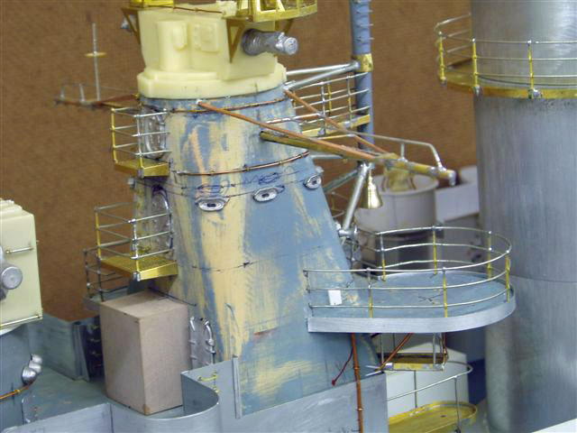
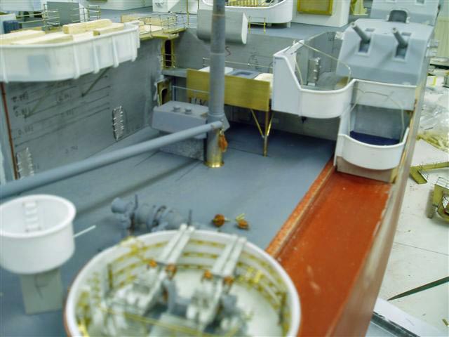
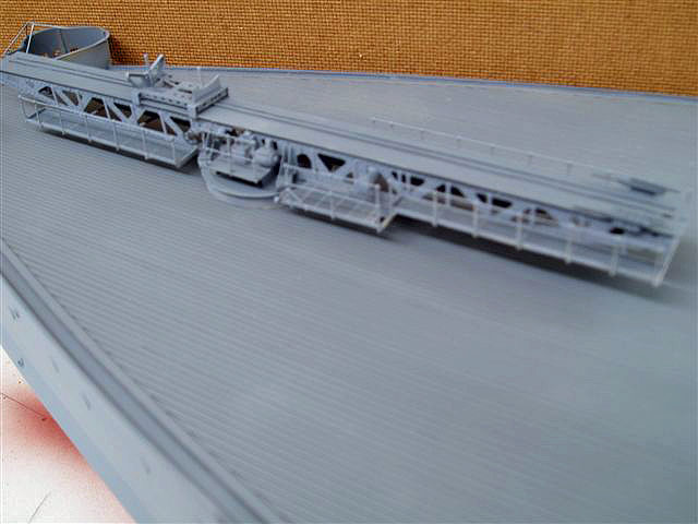
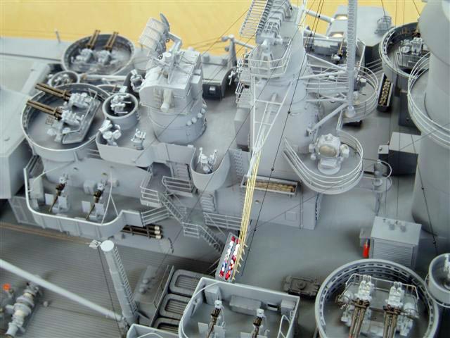
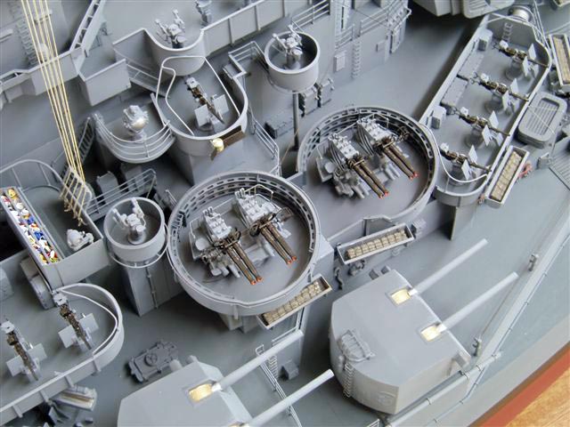
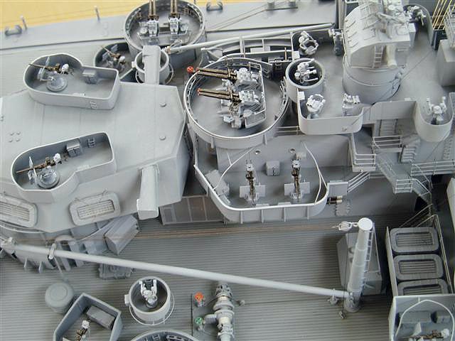
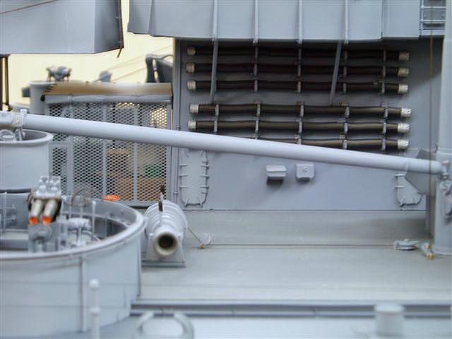
These are the final shots of the centre area , port and starboard . A lot of other work is still to be done elsewhere but the centre was the most difficult to understand from the plans . All sections of this are demountable to enable a decent finish to be provided , ie: vertical surfaces/ deck, different colours.

December 18 2006 update. John writes:
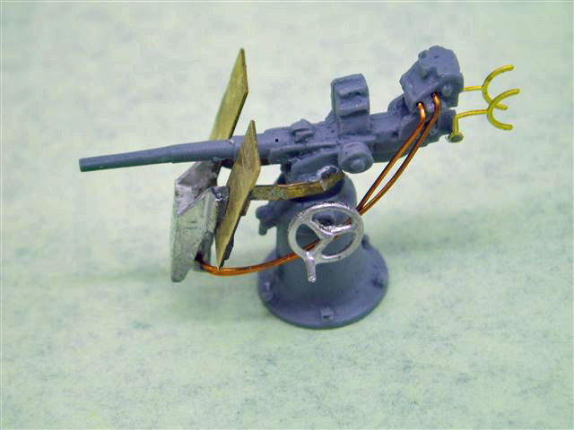
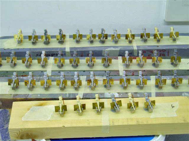
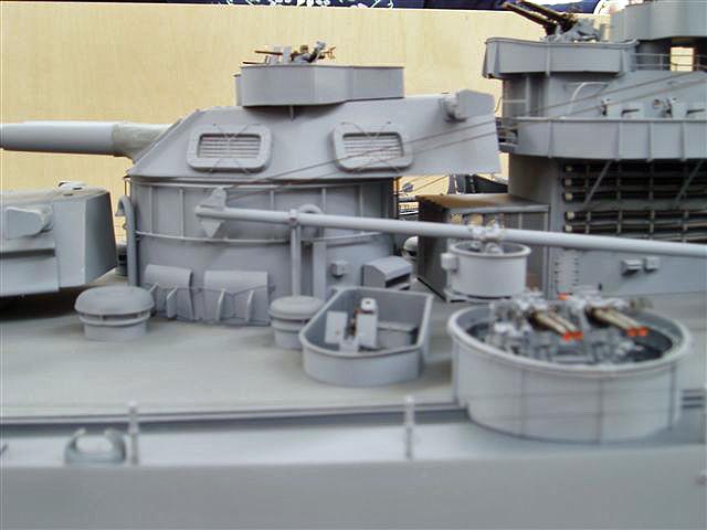
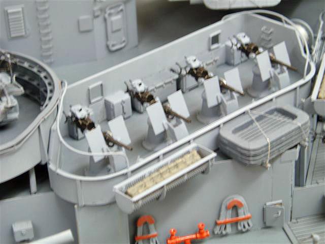
All the 20mm oerlikon mk 14 are now complete. This item is part number JRH 109 and all the 40mm bofors JRH 80 . On this ship no 40mm shields were fitted but on my JRH 80 you get the PE shield and sights together with the training handles and backrest. The rear armoured top now has the outriggers and bell , all the mk 37 directors are complete, which were built using my JRH 118. Maybe its all downhill from now ? !!!


January 7, 2007 update. John writes:
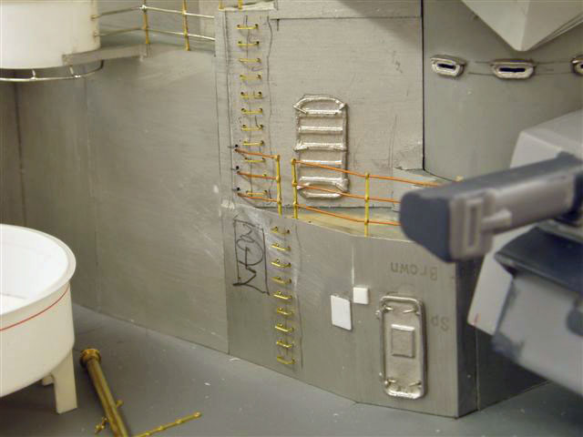
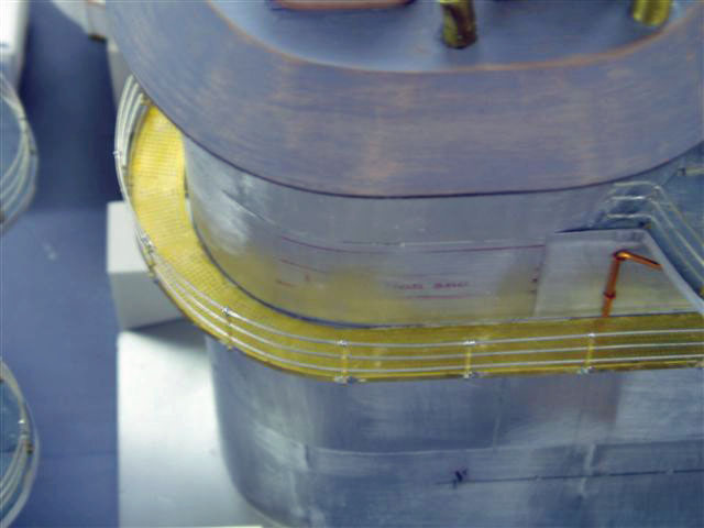
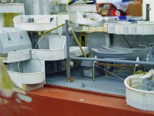
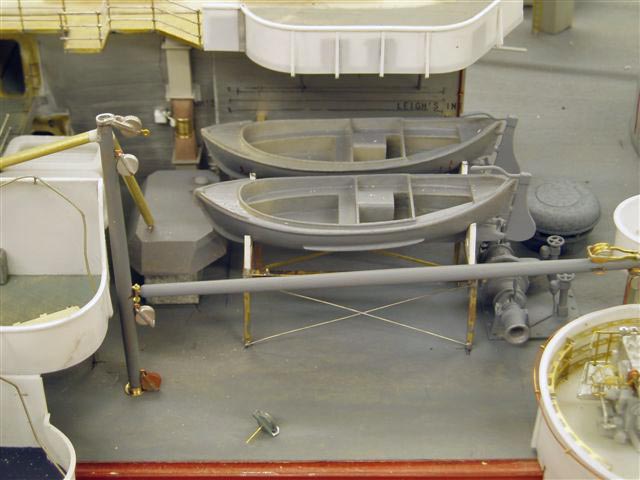
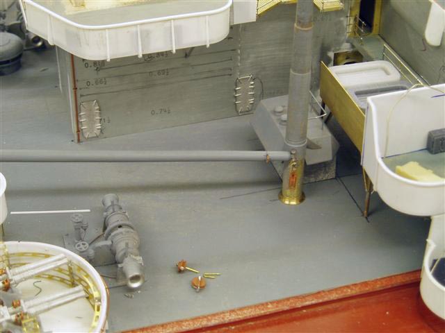
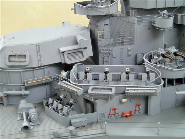
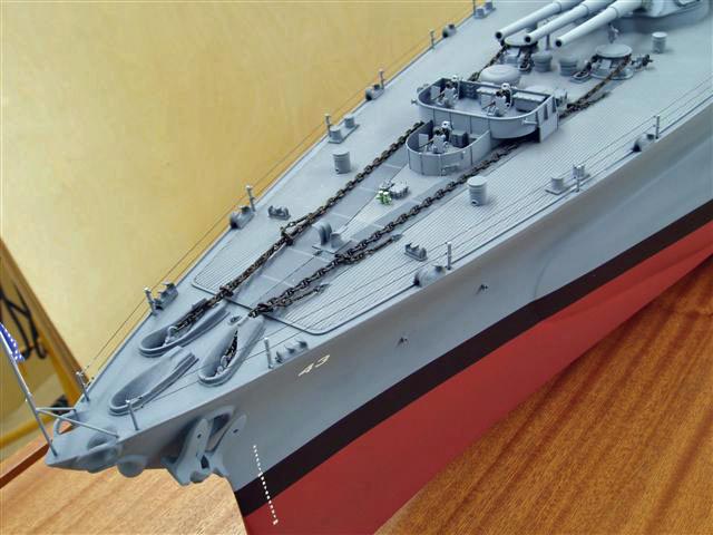
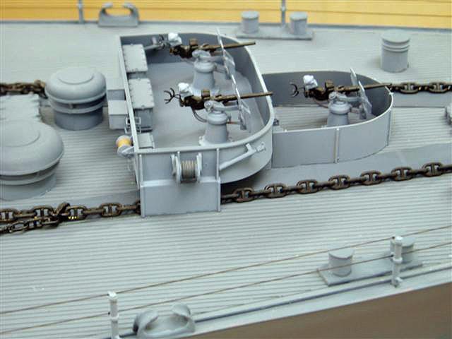
I have been working on the focastle break and the two boom arrangements, each different. Also the raft supports at this station and the two large rectangular vents with electrical terminals on top. I have started to put on the pipe rails around the 20mm tubs which prevent the gun firing into the ship superstructure. All these structures are demountable to spray finish so eventually I get to put a kit together

January 27, 2007 update John writes:
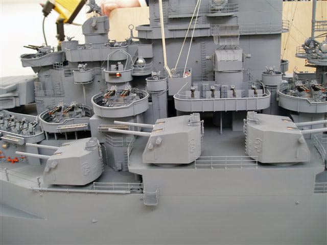
All the detail has been added to the bulkheads, the barbette detail also and all the depression rail around the gun platforms. The 5".38 turret outfits are complete and this will be the last raw build detail photos before the model is disassembled , individually sprayed and put together . I will issue photos of this part of the build process in due course


February 7, 2007 update
The catapult was only partially correct but I managed to get it together . If I run this I will need modifications and a new set of films etc but will wait to see if there is a demand out there first.


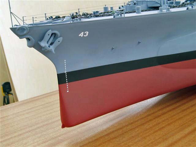
Spraying has begun. The deck 20B and the 5N have been considerably lighten with 5H to lose the toy effect that these colours in there true form tend look on a model, to reduce that, a scale effect is necessary.
February 27, 2007 update


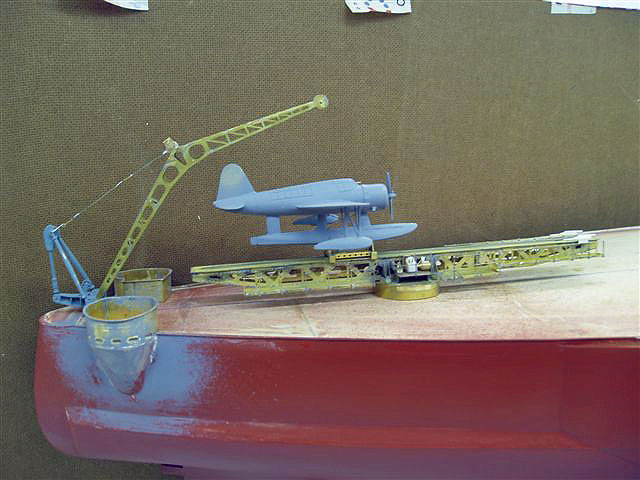
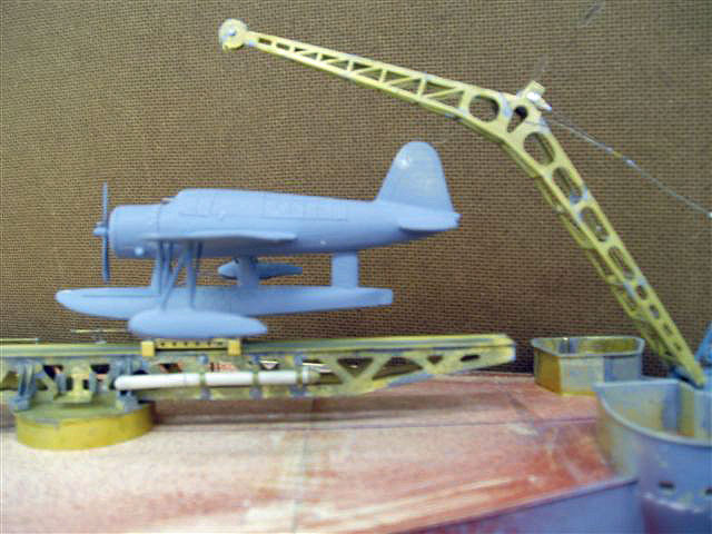
Here are shots of the Cruiser style catapult on Tennessee, now available as part number JRH 707. This is a two part fret , with one sheet of .018 thick and the other at and 1 at 1th . Am spraying up the model which is taking days to do , John
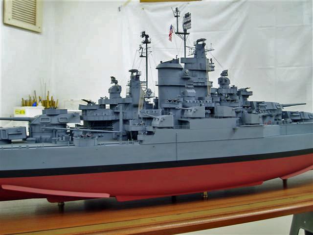
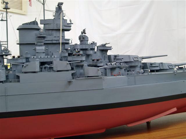
March 13, 2007 update
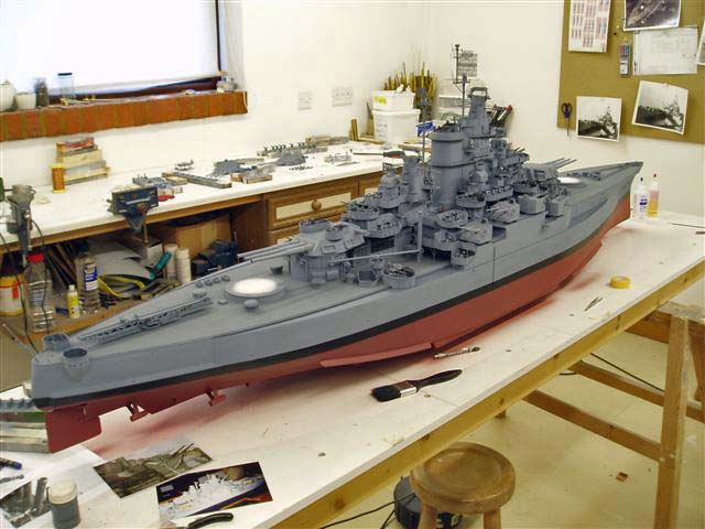
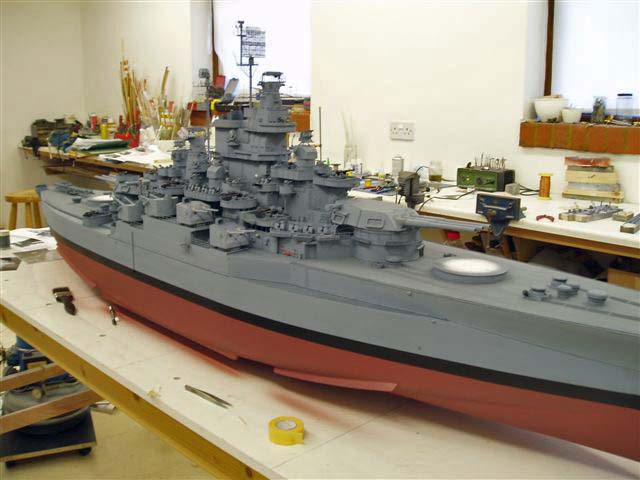

First painting!
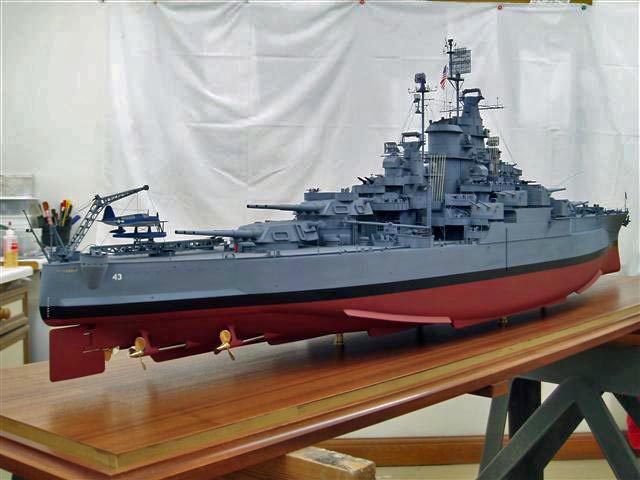
March 30 2007
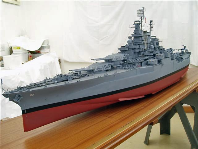
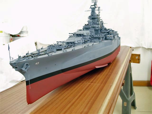
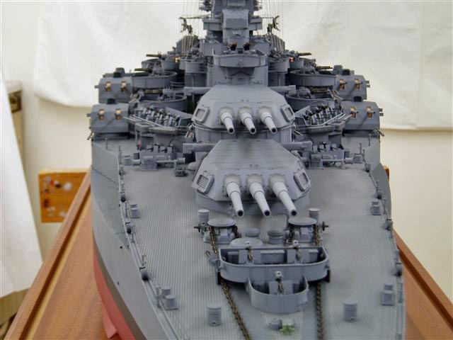
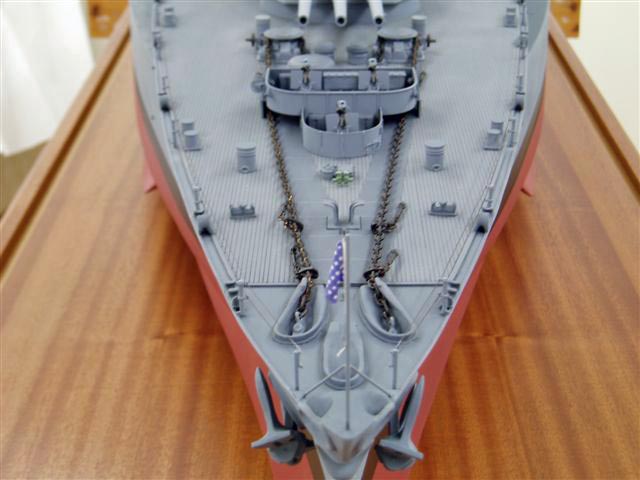
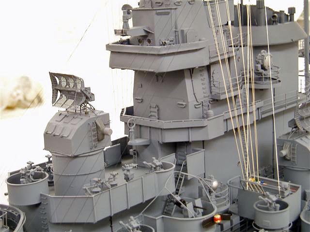
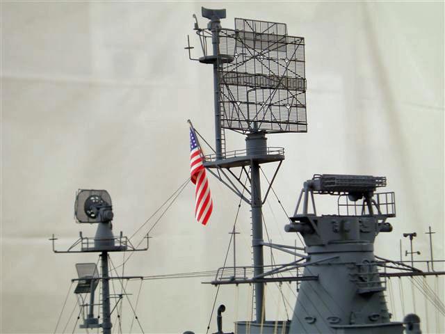
The completed model, ready for shipping.


![]()

Back to Warship Models Underway
This page maintained by Kurt Greiner. Email me here.
This page viewed 209
Version 1.41
Last update 3/07