


Click on any image that has a border to enlarge. -
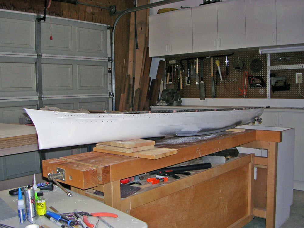
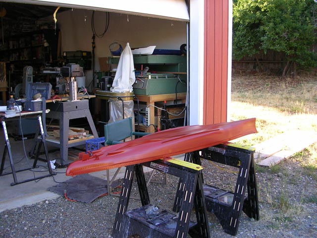
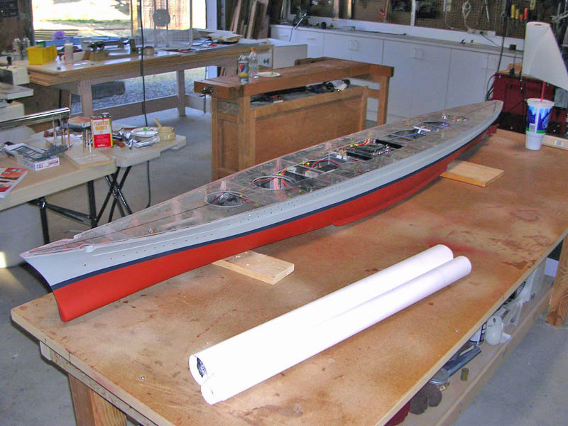
This is a 1/100 scale model being built using a Scale Shipyard hull. The master pattern for the hull was finished to a very high standard by Dave Manley of Small World Models, who is currently building her sister ship, the Scharnhorst.
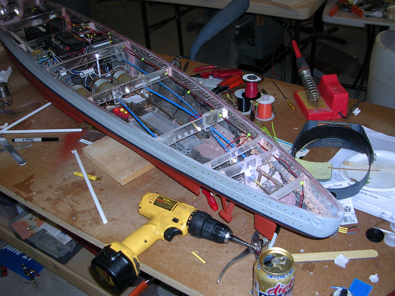
I believe in a neat electrical system, to both prevent problems and aid in troubleshooting in the event they creep up anyway. Over the years, I have come to find that a control panel that integrates power distribution works best for me. I use a negative ground system, where all grounds are grouped together off of a single common distribution point, usually a bolt embedded in a block of plexiglass
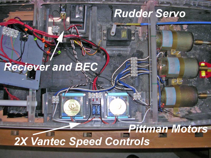
Overview of electronics with control panel removed
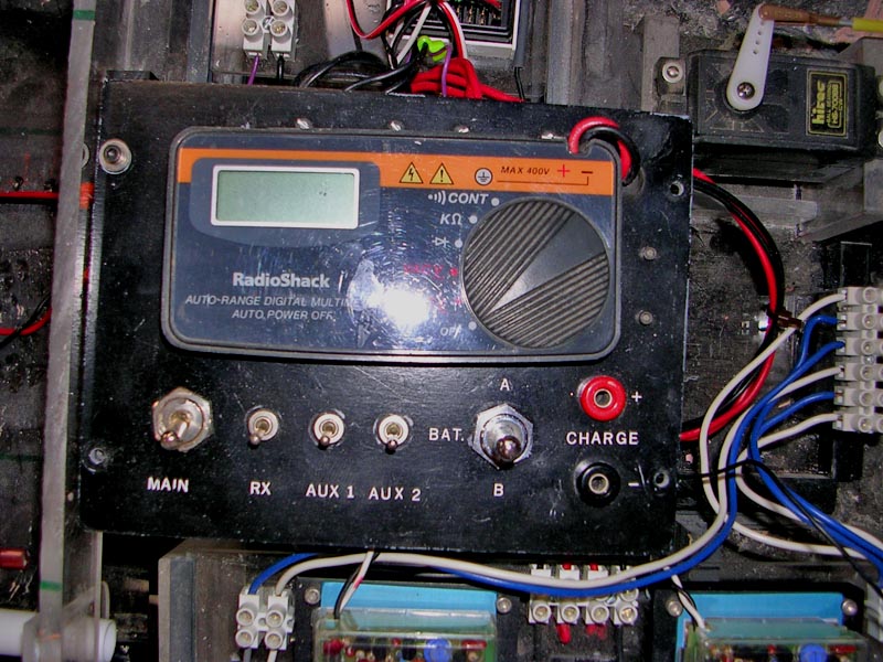
Front of control panel, showing integrated volt meter to monitor battery
performance. Two batteries are carried and can be selected via the
switch on panel, for either use or charging.
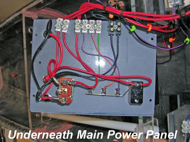
Back of control panel, showing wiring. A solid brass rod transfers
the power from the main switch to the three secondary circuits, which makes
installation cleaner.
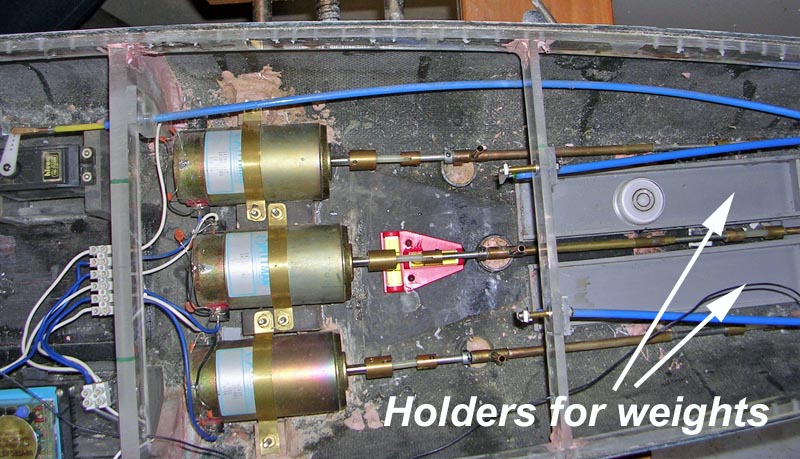
The motor installation. The three motors are Pittman industrial
servo motors, purchased from a supply house in Ohio years ago (sorry, they
are out of them now). They were installed in saddles made of Phenolic
(just what I had laying around). The motors have a 1/4" shaft, so I
had to custom make a Dumas style coupler to receive the dogbone.
A very common problem with r/c installations is how to access the rudder for maintenance. The rudder itself needs to be greased periodically, and often you cannot pull the propeller shafts without removing the rudder first. For many models, the answer is an access hatch over the rudder posts, to allow you to reach a set screw that retains the rudder post to the tiller arm. For ships with large flat decks, this results in an unsightly hatch that is a potential source for leaks.
On my USS John Paul Jones, the solution was to permanently embed hex wrenches in the model that could be pushed toward the stern to engage the set screws. Once engaged, they could be loosened and then the rudder removed. This system works, but the hex wrenches need to be withdrawn and ground down a bit as they wear. The set screws, though stainless steel, are a concern because if they become stripped, the flight deck will need to come off so they can be replaced. The system has been in use for about 8 years, and is workable, but I wanted to come up with something better.
Speaking to Dave Manley, he told me of a snap in system he was trying in his Scharnhorst, where you would insert the rudder from underneath, through a square tiller arm and it would snap into the top of a ball link. I though this was a big improvement over the system I had been used it, but was concerned about the life of the ball link; if it loosened, the rudder would fall out of the model. I opted for a more positive retaining system, using a sliding retainer made out of square tubing, pushed in an out with a Sullivan Gold-n-rod.
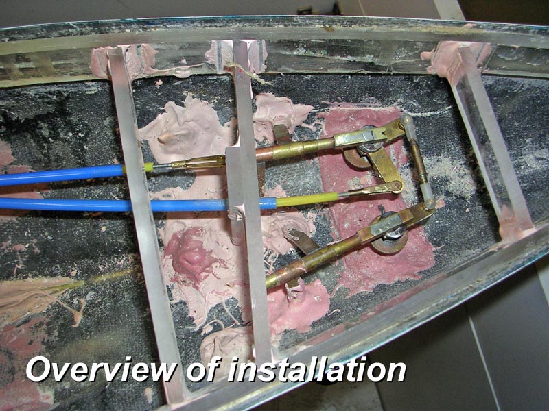
An overview of the installation
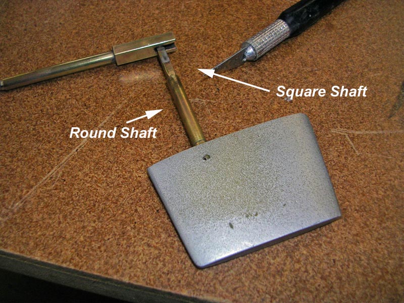
Rudder, showing round post where it penetrates the hull, and square section
where it engages tiller arm
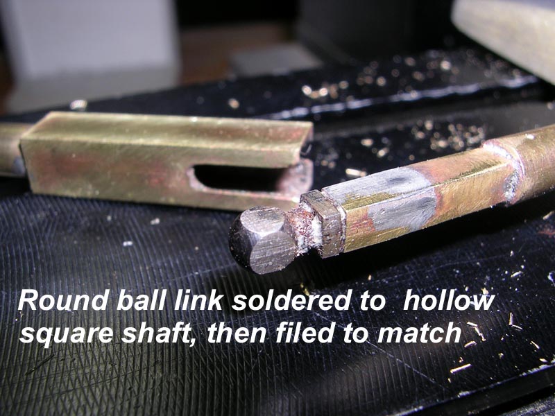
Top of rudder post showing ball, and the sliding retainer which engages
it

Looking down at the tiller arm with the rudder removed, you can see the
square piece of tubing that was soldered into place to receive the square
section of the rudder post. This creates a solid connection with no
play, and yet can be easily removed. I apply a small amount of grease
to the rudder post sections, both round and square, prior to installation.
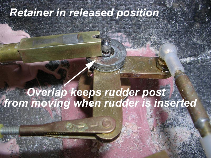
The retainer is made to slide back just enough to release the ball, but
no further. This keeps the tiller arm in place when the rudder is released.
There is a tube under the tiller arm the slips over one mounted to
the hull to prevent movement front to back or side to side.

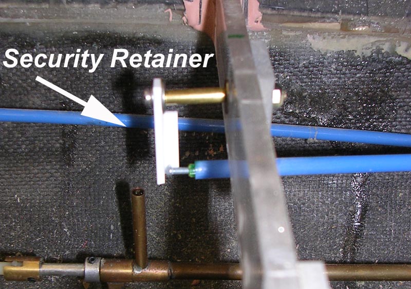
Mounted to the bulkhead just under the superstructure opening, the other
end of the cable is slid with a finger toward the bow of the ship about 1/4"
when rudder release is desired. The white piece of plastic acts as
a safety to keep the cable from vibrating forward and releasing the rudder
accidentally.
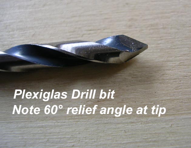
Well, she has a lot of them, to be sure. After soliciting some advice from the message board, I decided to drill them out and put plexiglas rod in them after painting. Drilling a fiberglas hull can be a problem, with the thin gelcoat on the outside having the tendency to chip. You can apply tape over the hull to minimize this, but it can still chip out when the tape is removed. I found a special drill bit at Tap Plastics (a local plastic supply chain in California) that was made for drilling plexiglas. It has a much more acute relief angle, and after drill a couple of hundred holes with it on the side of my hull, find it works great. Here is an online source that I found, but I have not done business with them yet, so you are on your own here.

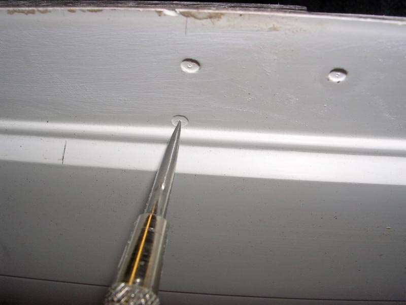
The ports on this hull were marked by shallow depressions, saving me the
time to mark out and locate them all. I first put a small indentation
in the center using a sharp punch.
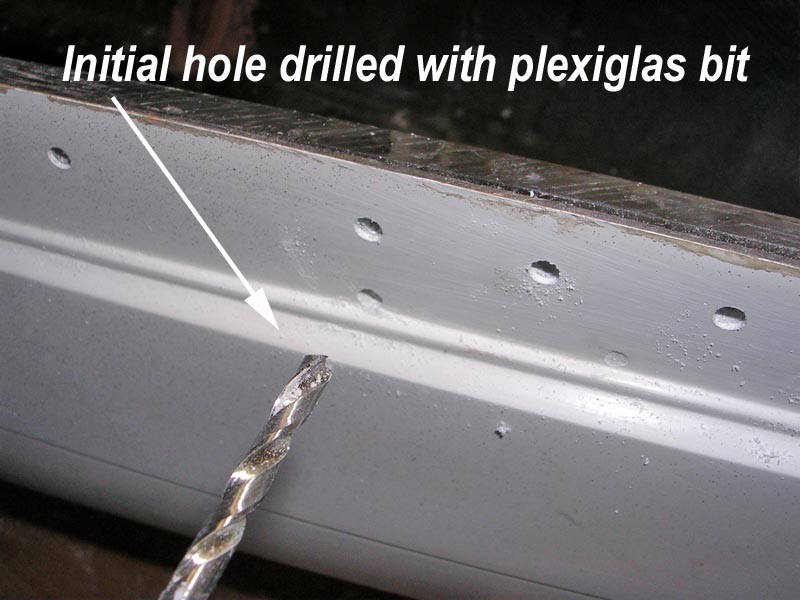
I put the sharp tip of the drill bit on the center mark, and squeezed the
trigger of the drill for a couple of revolutions. I took a look at
the mark, and if it was not centered, could easily "steer" the drill at this
point to get a perfect start I then drill, using a slow speed, until
the drill went into the hull and just started penetrating it full diameter.
At that point, I switch over to a conventional twist drill to go through
the bondo and plexiglass behind the hull. After experimenting with
drill straight through with the plexiglas bit, I found this technique worked
better for me.
July 6, 2006 update
A lot of work, which doesn't show all that much LOL. Ports have been drilled, hull primed and painted, ports polished and ready to install.
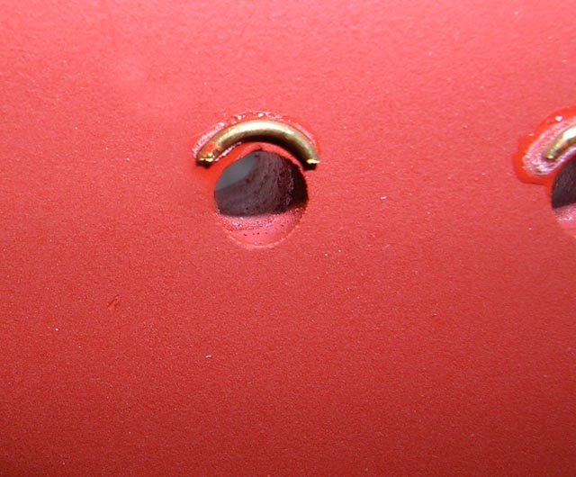
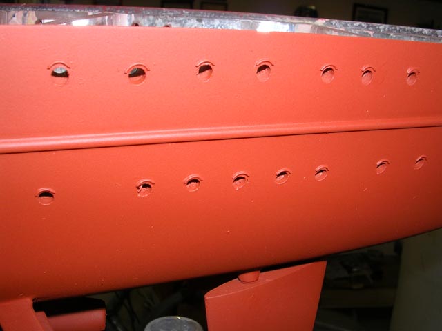
Eyebrows are made of .020 brass wire, wrapped around a mandrel the same size as the porthole - when the wire relaxes, it is slightly larger and a good radius for the part. They are cut with a pair of flush cutting wire pliers, and then positioned into place above each port. A drop of superglue secures them, followed by a coat of primer.
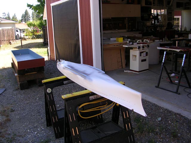
This was a good point to flip the hull over and fill those little dings and scratches, and then put a coat of primer over the whole mess
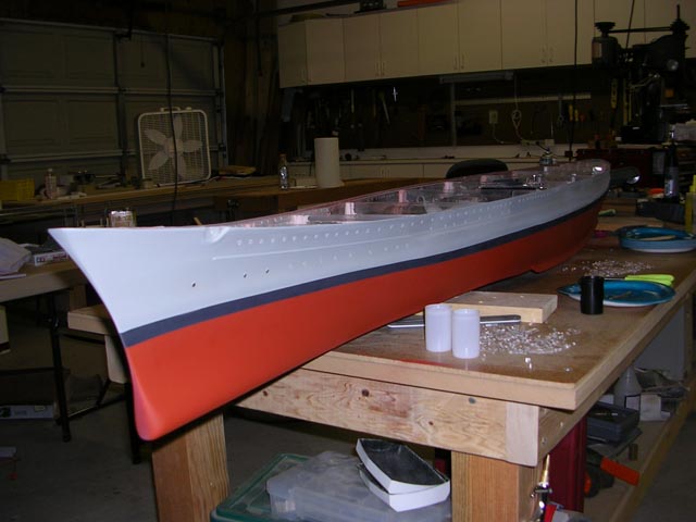
I used Duplicolor red primer for the hull, Testors Model Master Light Sea
Gray for the hull color, and Model Master Flat Black, lightened a bit with
Gunship Gray for the boot topping.
Having put clear ports in, I thought it would be nice to have some internal illumination for night runs. Now, I well realize that the Gneisenau did not run with this sort of reckless disregard for light discipline, but it will make for a pretty sight out on the water.

I used 3.6 volt white LEDs for the internal lighting. I chose these because some would be inaccessible after the deck is installed (at least, without drilling). These LED's have a service life of some 10,000 hours, so they should be safe in this application. This page was very helpful in learning to use these devices. For my ship, I am running three circuits of 3 LED's and one 51 ohm resister each, with all connected in series.

They are mounted at various points in the ship, to give as much light as possible despite the obstructions (barbettes, batteries and so forth). I used a through support beam mount for some, and a pedestal mount or bracket for others.
With the lights on, the effect is subtle - not the Love Boat, but reasonable at night.
The Deck was make out of 1/8" acrylic sheet. I laid it over the hull, marked out about 1/8" i n from the hull with a sharpie, and cut it out using a Rotozip. Openings for the deck and barbettes were made in the same way. More on using the Rotozip below. I am not worried about an overly neat cut at this stage, as the gap between deck and hull edge will be filled with catalyzed body putty.
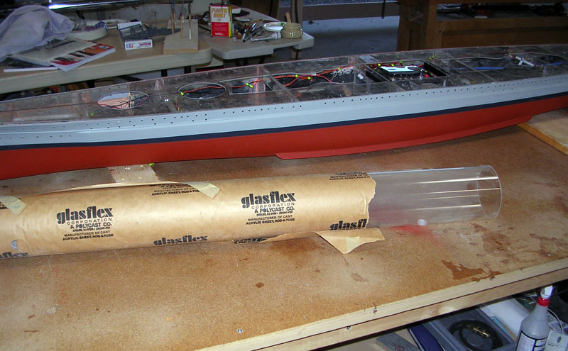
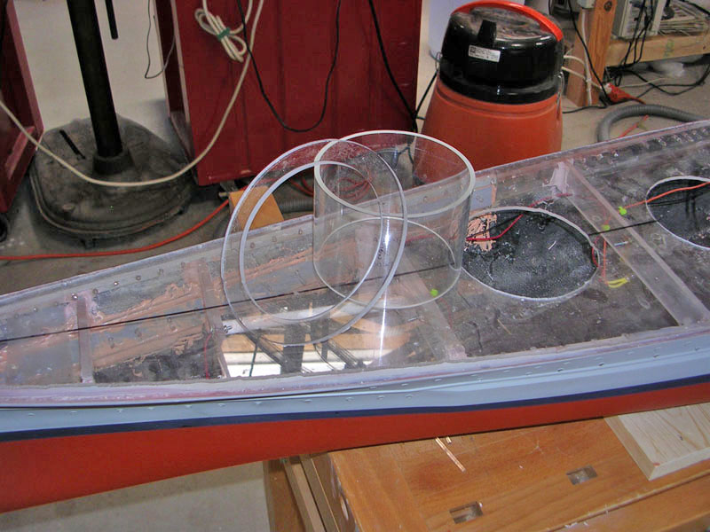
The Barbettes on the Gneisenau are made of 4 1/4 inch acrylic tubing. I had purchased a length of this years ago, some being used on an earlier project. Cutting it is a pain - I have tried bandsaws and other power saws in the past, but the material shatters very easily. The best way I found to cut it was to use a Dremel abrasive disc, and work my way around it slowly. After the tubing is cut, it is sanded using a 90 degree square to make sure it is true.
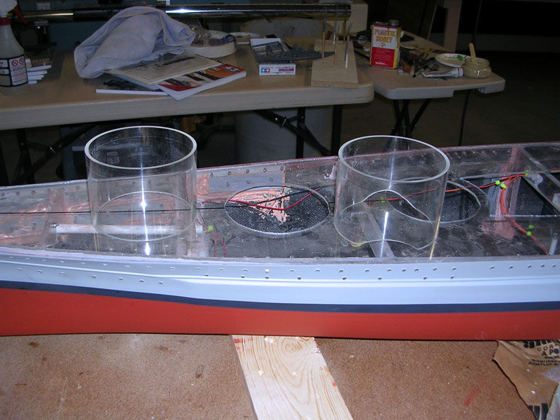
The 1/8' acrylic deck is too thin to support the barbettes, so reinforcement rings were made to be glued under the deck and receive the barbettes. These need to be cut accurately on the interior for good support.
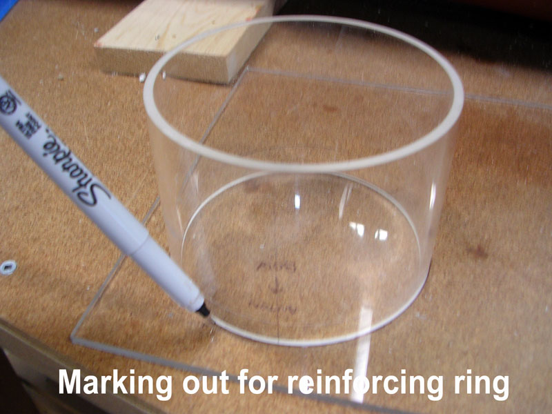
The barbette is laid on a sheet of 1/4" acrylic sheet, and a fine point Sharpie marking pen is traced around the perimeter
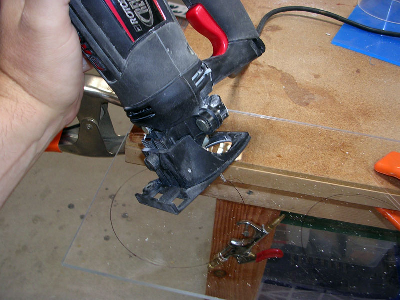
A Rotozip tool is used to make the cuts. I find this puts less stress on the plastic than other cutting methods, and have never had a piece shatter while using this tool (unlike jigsaws). If you don't have a Rotozip, you can use their blades mounted in a Dremel tool (better with the base attachment), but you will need to let the tool cool off during use, as there is quite a bit of strain.
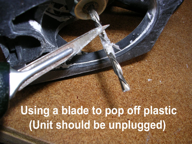
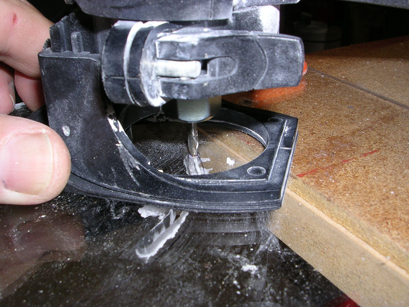
Check the bit from time to time, as plastic can melt on it, covering the cutting surface. It will still plow through material, melting the plastic from friction, but it puts a lot of strain on the motor. Unplug the tool, and use a sharp knife to pop off the accumulated plastic after is has cooled for a few seconds.
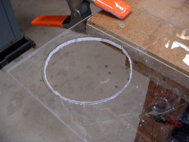
At this point, the inside is roughly cut. It will be finished to final dimension by sanding
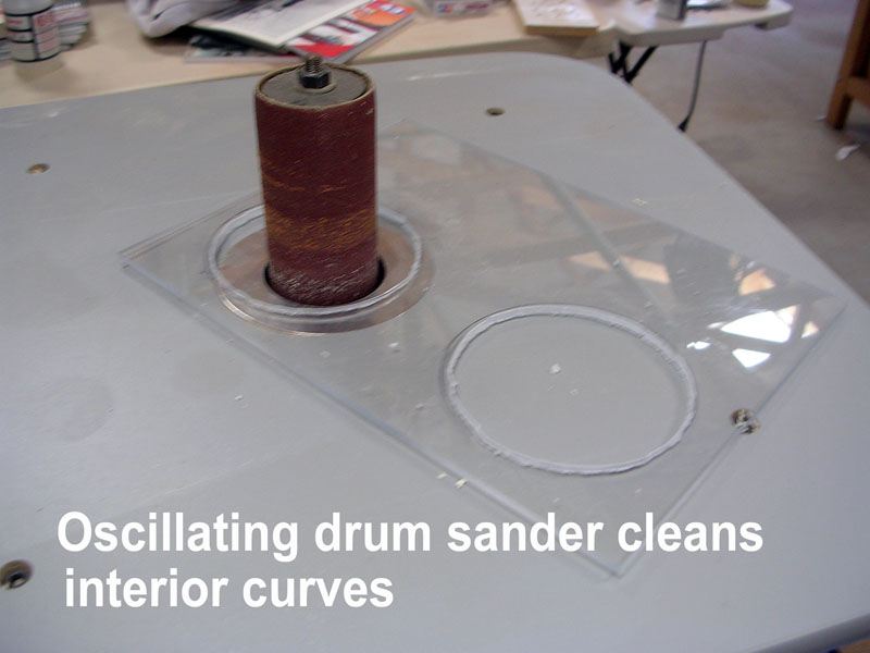
This is a very handy tool for this operation. It is an oscillating drum sander, made by Craftsman and was sold through Sears. I am not sure if it is still available, but I know that Delta makes an equivalent unit. This is a great tool for frame sanding too. You can use a Drum sander on a Dremel to accomplish the same work, but it will take longer.
Ok, I admit it, I am a tool junkie...
The goal here is to carefully sneak up on the final dimension, so that you have a nice slip fit for the barbette.
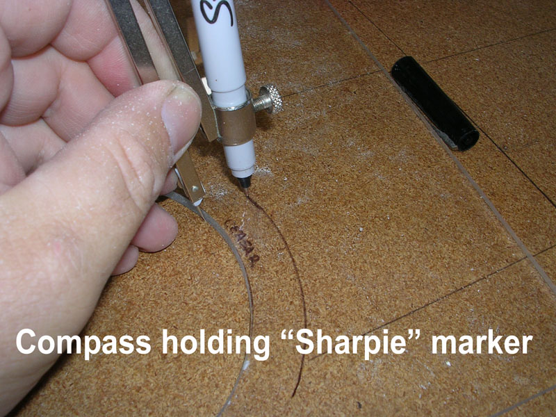
I have a compass that can receive a Sharpie market, and I use this to set out an outside ring dimension, as it is not critical.
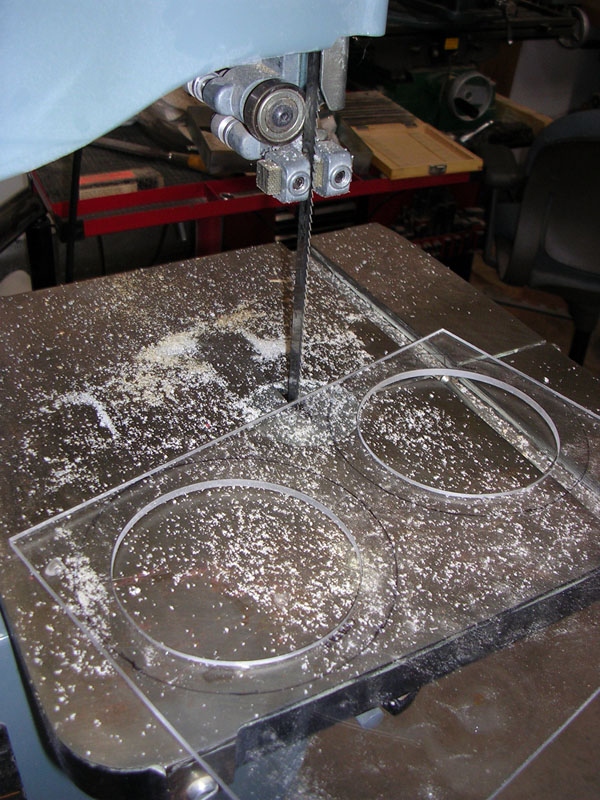
The rings are rough cut on the bandsaw...

...and finished on the sander.
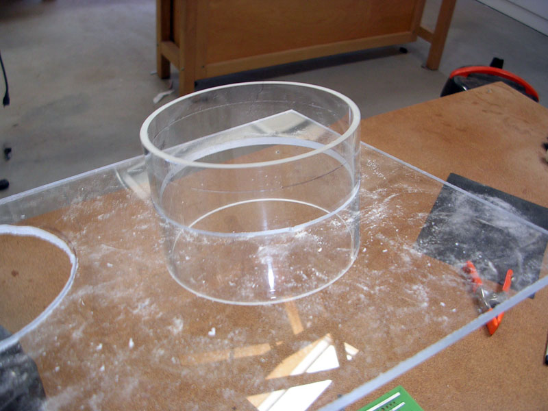
The finished deck ring and barbette. When it is time for installation, the ring will be slipped under the deck, and the barbette pushed through to proper height above deck, allowing for the thickness of deck planking. The ring can then be glued to the underside of the deck at this point, and the gap between the deck and barbette filled with Evercoat.

The 01 Level starts with a sheet of .060 Lexan, a brand of Polycarbonate plastic sheet. This is laid over the plans using weights at the corners to keep it stable while marking
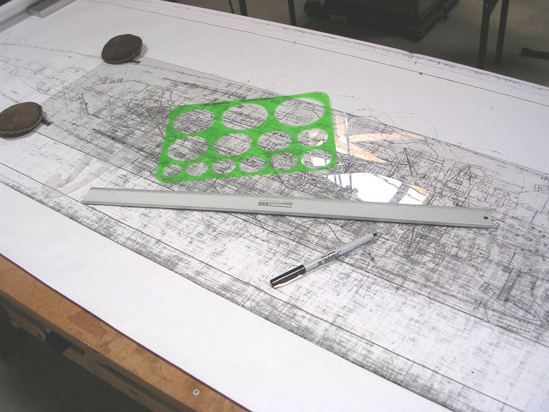
You can trace over the lines freehand, or use drawing aids such as circle templates and rulers to keep everything neat. A clean Sharpie (red seems to work best for me) is used for the tracing.
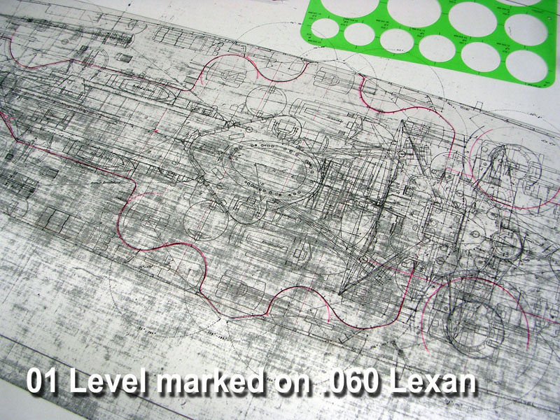
One the level is marked - and double checked - it was cut out using a bandsaw, rotozip, power and hand sanding, finishing with small files in the inside curves. It was a fair amount of work and took a few hours, but care here is important as it establishes the baseline for everything else above the deck.
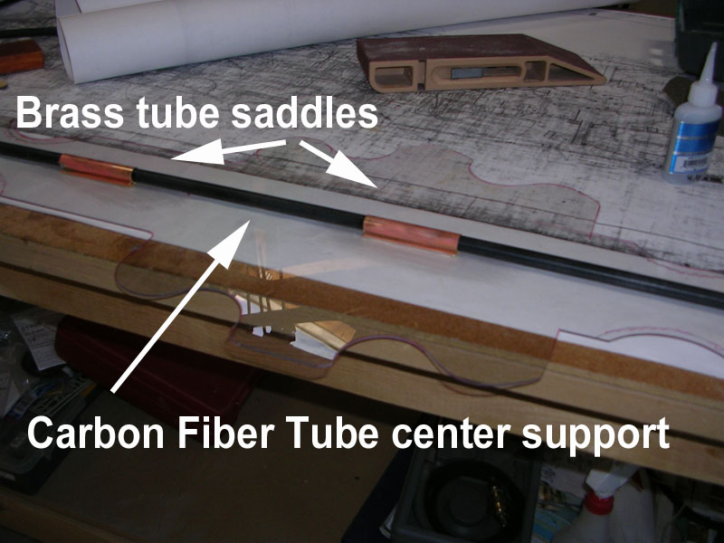
A piece of carbon fiber tubing is threaded through brass tube saddles to give support to the narrow superstructure. Once the bulkheads and internal Sintra supports are in place it will be a nice and rigid structure, which is important because of the uneven loading on the levels above..
The bulkheads are made out of 2mm (.080) Sintra, a foamed PVC sheet (Here is a page with some more information on using it). It is rigid and lightweight, and very easy to work.
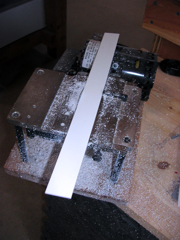
The first step is to strip the Sintra into the height of the bulkhead. Be sure to take into consideration the height of the deck planking, if any, and the thickness of the roof. Sintra can be stripped using a knife and straightedge, or a full size table saw, but the little Preac saw does a really nice and fast job of it.
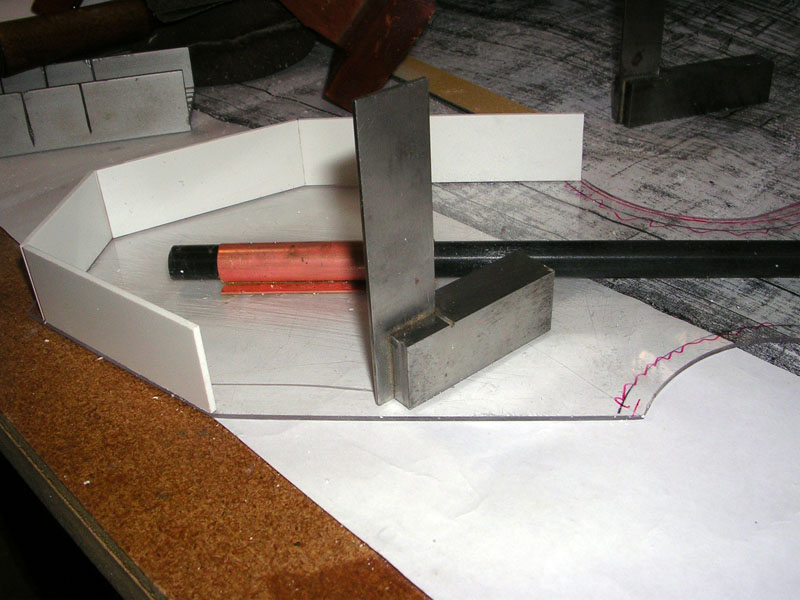
The sections are glued into place with thin CA, using a square to keep the bulkheads vertical to the roof.

The roof is used as a guide for marking each piece, a small tick with a Sharpie indicating the cut line
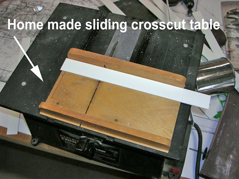
The sadly defunct Dremel Table saw is used to crosscut the pieces. A homemade sliding sled insures that each strip will be cut square. The kerf cut in the table makes lining up the tick mark very easy, as you can see exactly where the cut line will be.
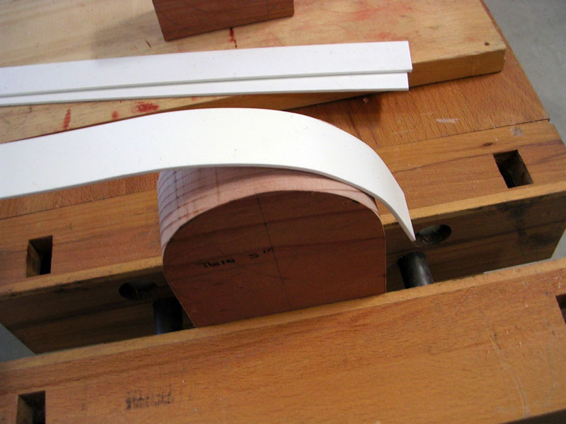

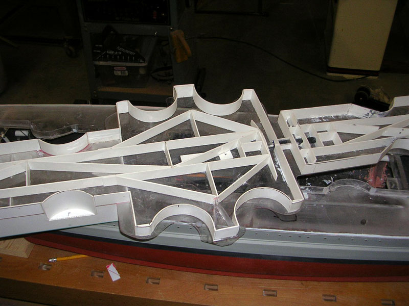
My personal belief is that the Kreigsmarine intentionally made their superstructures complex to frustrate future Allied model makers. To form the multiple curves, patterns were made from redwood, and the Sintra strips were formed using a heat gun. The heat gun gets very hot, and I think next time I will try the process with an ordinary hair dryer.
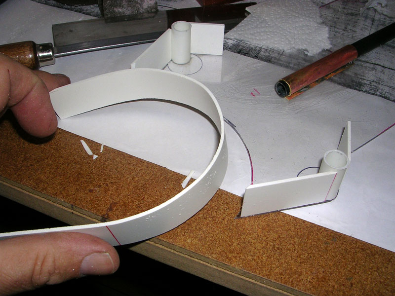
Once the strips are formed, they are set into place, and the cut lines marked. The strips are cut with the table saw sled, as before.

It took a while, but here the major sections are glued in place and read for putty.
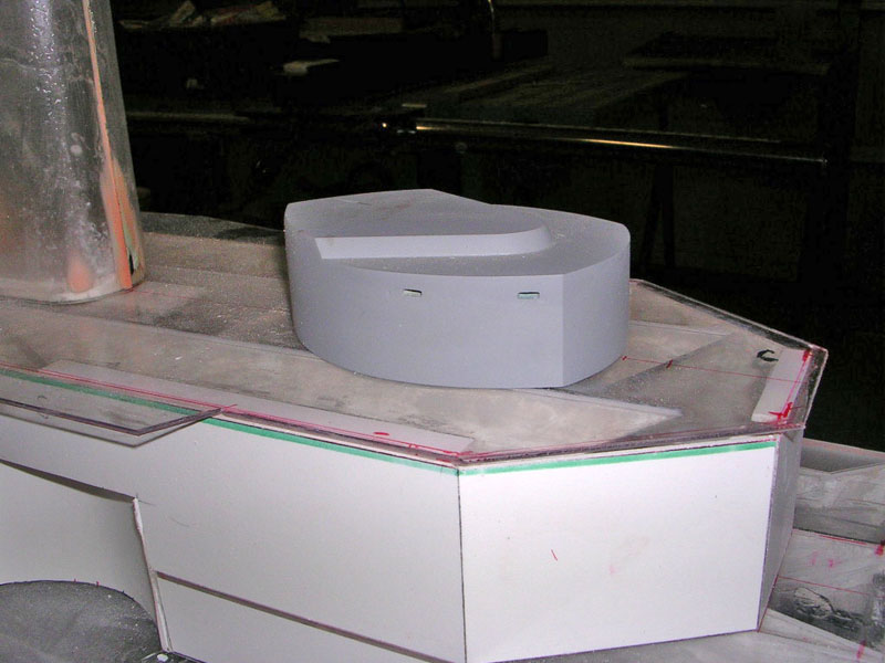
This structure will support the upper decks and range finder. There are a lot of ways to build it, but I like to vac form the outside over a strong central support.
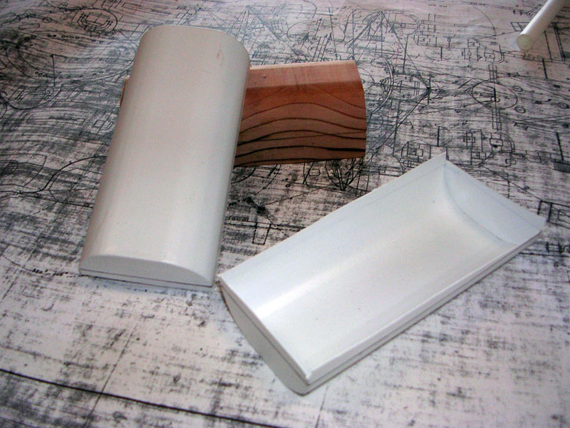
A wood half pattern was made and sanded, and then .040 styrene was vac formed over it, to form the outer shell
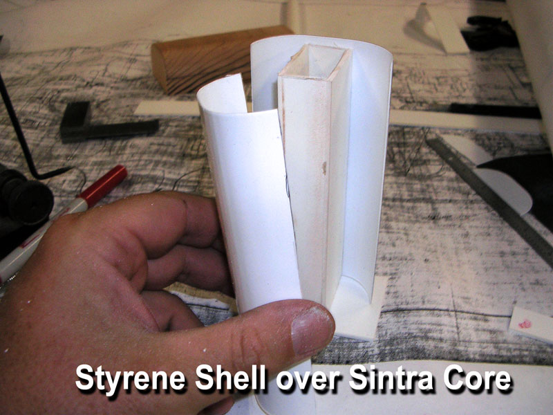
A box core was made from strips of Sintra glued with CA, and then the flat sides of the out shell were glued to one side
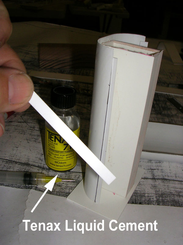
A strip of .030 styrene was glued to the outer edges to form a lip which will receive the other shell side
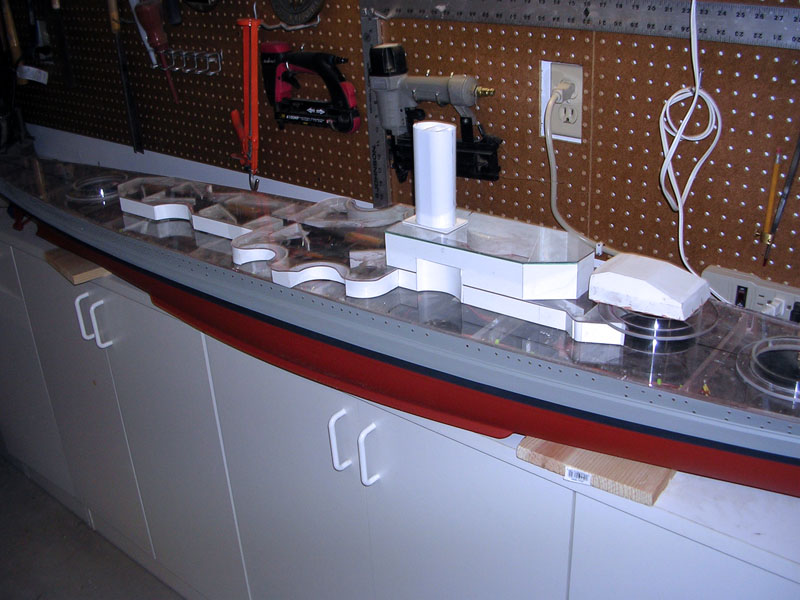
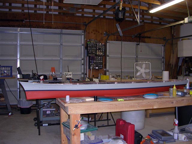
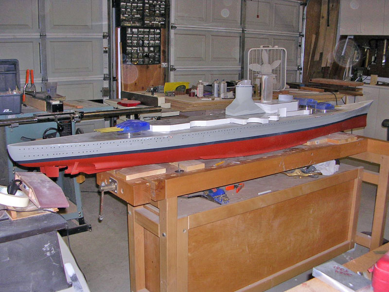
An overview of the project on July 15, 2006
I have been doing a bit of work to the old girl lately, but I needed to get this pattern out to Dave Manley of Small World Models for casting due to lead time.

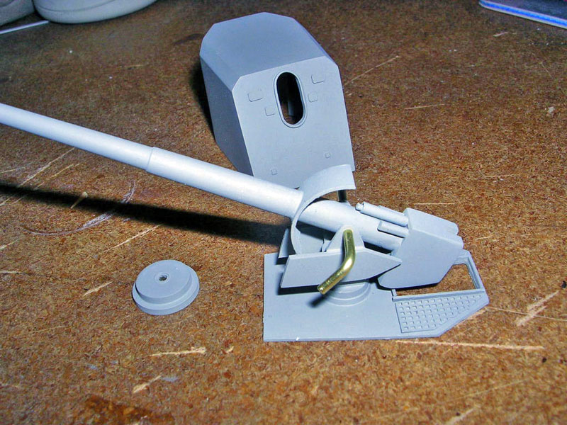
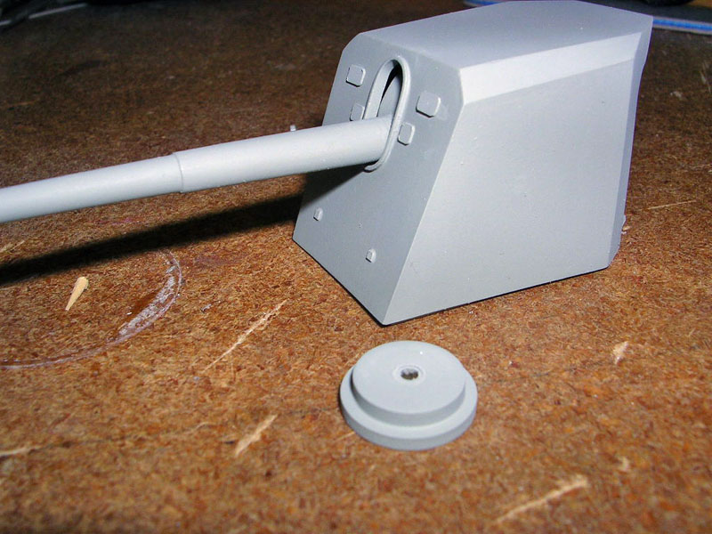
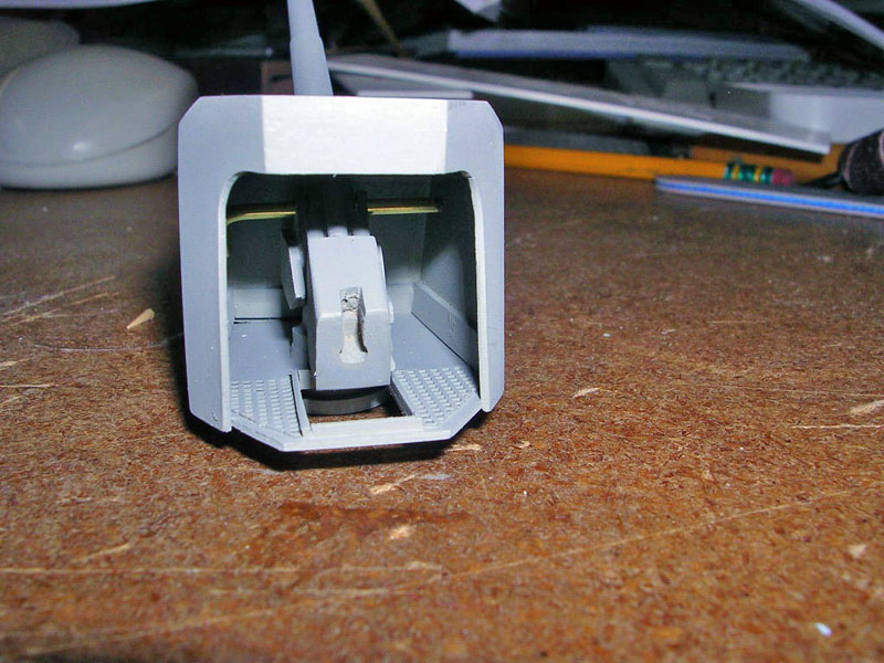
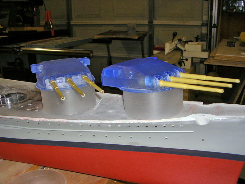
Dave Manley of Small World Models built the pattern and cast up these beautiful turrets.
I replaced the single carbon fiber rod seemed like a good idea, but it expanded differently than the rest of the superstructure, causing a bow. If I were to use it again, I would mount it in saddles where it could slide freely, but really, these strips of sintra are working out pretty well too.
To prevent the ingress of water while operating, a coaming made of Lexan strips is installed around the perimeter of the hull openings. The strips are about 1/2" high, and are bonded to the Plexiglas deck using Tenax 7R solvent adhesive.

To make painting and repairs easier, the main components of the superstructure will be bolted together instead of glued.

This piece started life out as a solid block of plexiglas, which was sanded to shape and then hollowed out to reduce weight. A floor of 1/4" Sintra was glued into place, along with a roof of 1/16" Lexan. The bevel on the top is a 3/16" piece of plexiglass that was sanded to shape on a belt sander with the table angled, glued, and then blended into the piece using Evercoast. The view slits were hogged out using a Dremel Tool, and then a plug was made using styrene in a male shape representing the port. The plug was coated with WD 40 as a mold release. Evercoat was troweled into the hole, and then the plug, which has strips that help locate it, was pressed in until the putty gelled, and then carefully removed, leaving a perfect female impression. The extra putty that swelled out was trimmed with a razor blade at this point, and then sanded when dry.
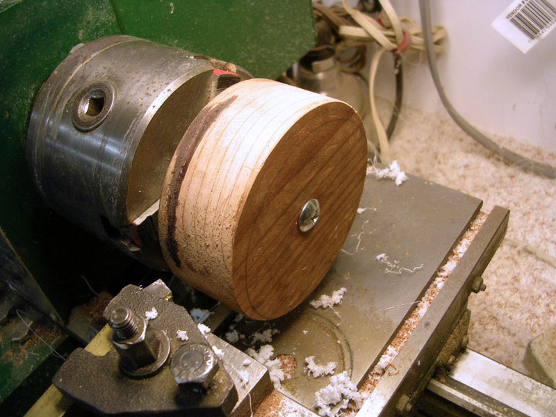
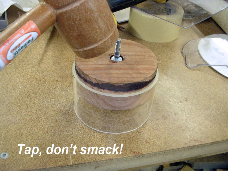
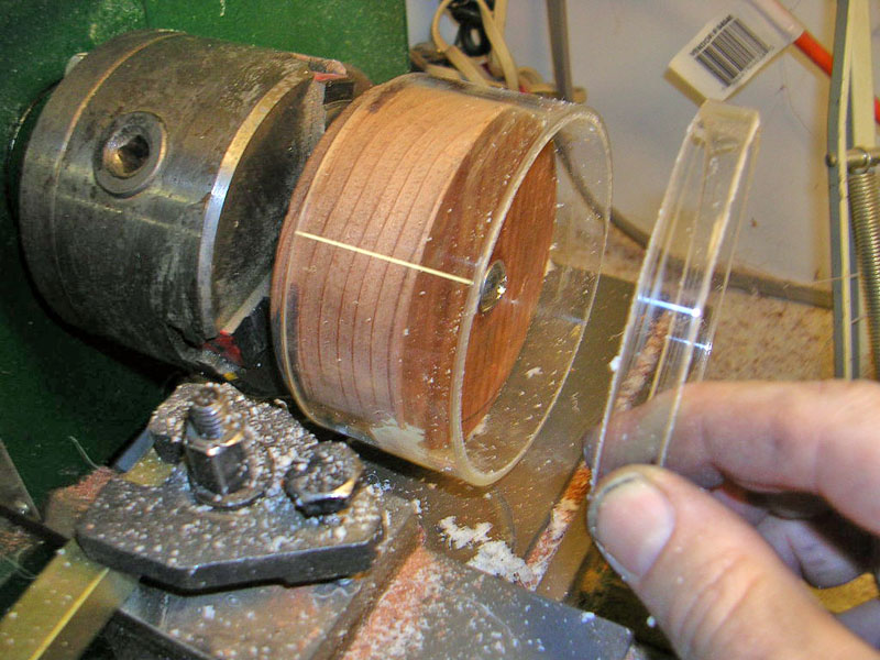
I use plexiglass tubing for my barbettes, as it is thin, easy to glue and available in the right size for this application. Cutting and turning this material can a problem, as it is brittle and prone to shattering. I solve this by turning a plug of wood so that it is a press fit inside the material. and using this to hold it on the lathe instead of the three jaw chuck. You want the fit tight enough that is requires light tapping with a hammer to gently seat it. If you overshoot the mark and the fit is a bit too loose, you can tighten it by applying water to the plug, causing the wood fibers to swell. You can also wind masking tape around it, but more than one layer can cause slippage - better to try again with a new piece of wood.
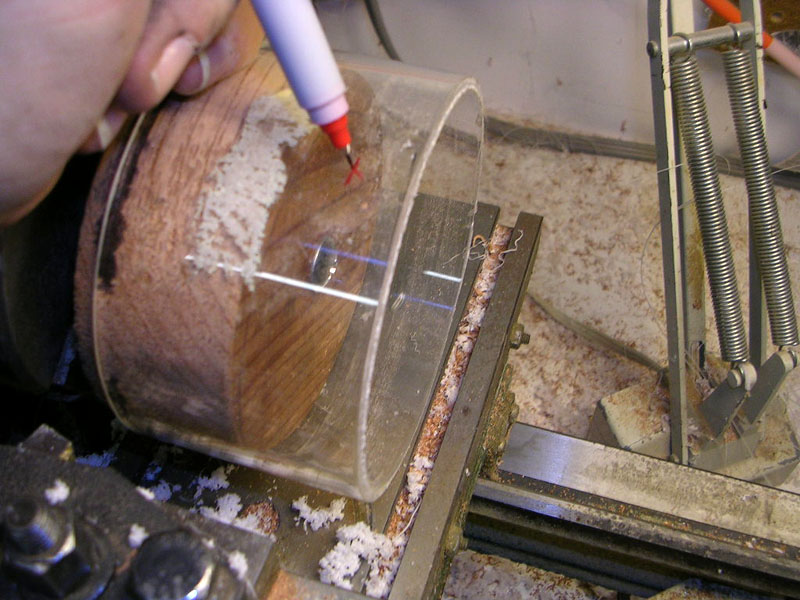
The length of the tube is marked by putting a tick with a Sharpie marking pen, followed by a line drawn my rotating the head lightly against the pen by hand.
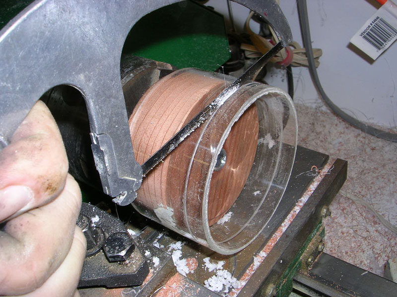
There are a couple of ways to trim the tube to length, but I like to carefully use a miniature hack sack taking very light cuts until the ring is parted. You will need to get a feel for this operation, and maybe shatter a ring or two (or three) in the process, but once you develop the technique, it works better than any other method that at least I've tried
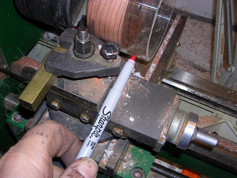
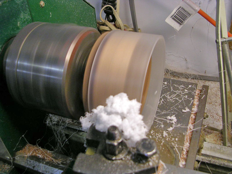
My system for working turrets uses to cylinders inside each barbette. Although the tubing ostensibly is nesting, the fit is too tight for free rotation. I take about .040 off the sides to get a nice fit. You want a nice puffy swarf off the lathe bit, not a string that can get caught up in the works. Sharp tools and proper tool height make the difference here. I use an old paint brush to clear the chips away - don't get near that 3 jaw chuck with your fingers when it is turning - it bites!
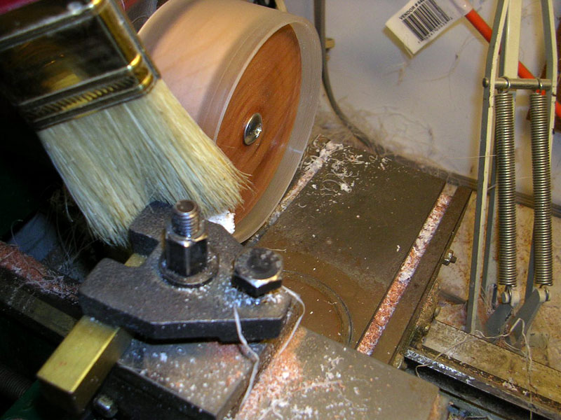
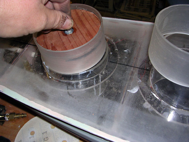
To check the fit, I keep the piece on the mandrel in case it needs further turning. If you dismount it, there is always the chance you will not get it on the same way, which may cause and unwanted error or taper.
November 18, 2006 overview of the project

![]()

Back to Warship Models Underway
This page maintained by Kurt Greiner. Email me here.
This page viewed 61
Version 1.13
Last update 11/06