


Click on any image that has a border to enlarge. -
John Anderson's USS Nimitz (CVN-68) in 1/96 scale is on Gallery 46A
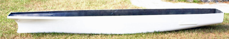
The hull as received from the Scale Shipyard
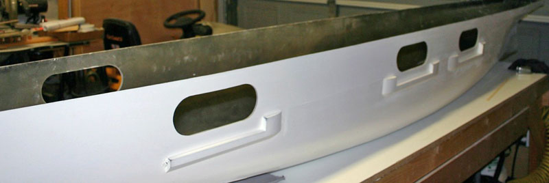
Started on the hull opening to the hanger deck
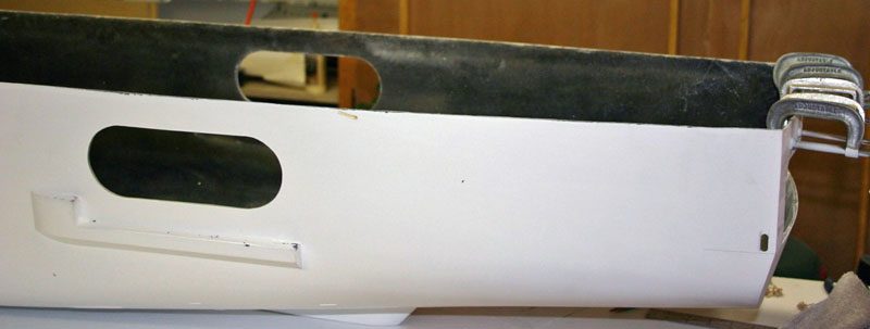
Port side hanger opening and the opening on the stern is for access to the CIWS mount located at that spot.
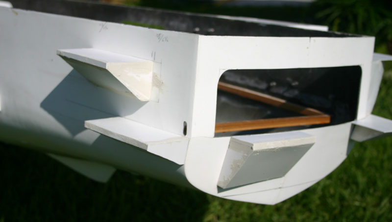
Here are the mounts for the Sea Sparrow launcher and the CIWS as well as the stern sponson. Here they test jet engines out before they go back to the aircraft.
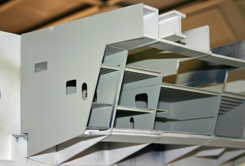
The beginning portion of the port side sponson that is located under the flight deck, lots of frames here, had to careful on layout for all of the openings and vent that are located within the sponson.
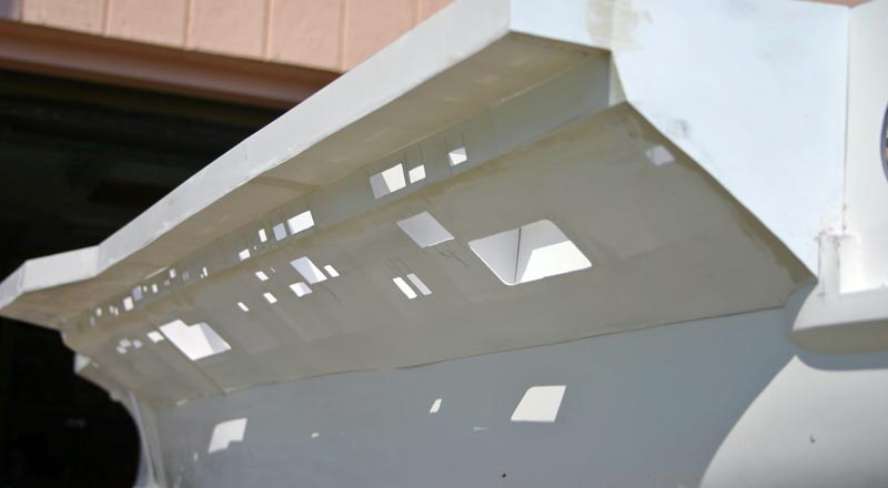
Stbd side sponson; the crane is located on the fwd most part of the sponson, and the Seasparrow and CIWS are located on the aft section. Once again had to be careful on locations of frames and reinforcements do to the opens and vents.
Stbd side sponson located between the two fwd hanger bay openings fwd of the island.
Stern shot showing the opening at the stern, where the jet stand and other equipment will be located.

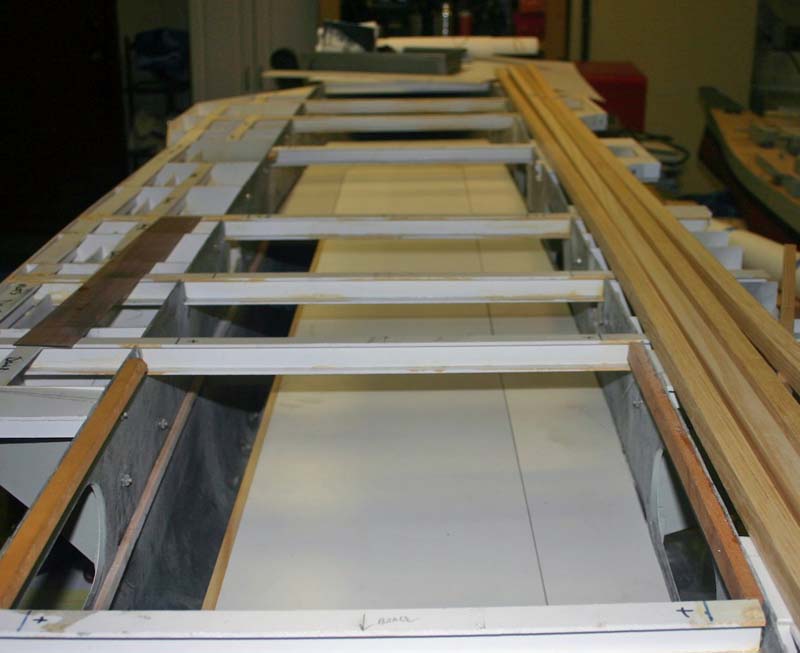
I-Beam: Here is one of the I-beams that I have built that will go under the flight deck to give it the support that it will need while keeping the upper portions of model as light as possible.
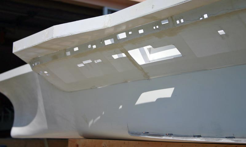
Port1: Fwd portion of the port side sponson with the vent and open deck locations cut into the styrene.
Port2: Aft portion of the port side sponson
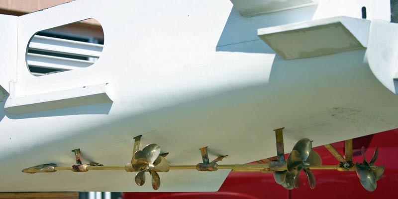
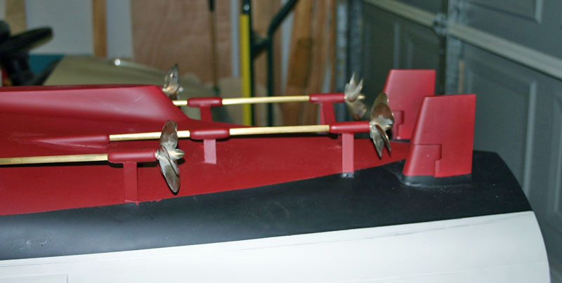
Port3: Aft port side showing the shafts and props that have been installed

Stern1: shows an overall above view from the stern showing the I-beams that have been installed up to this date.: Fwd portion of the port side sponson with the vent and open deck locations cut into the styrene.

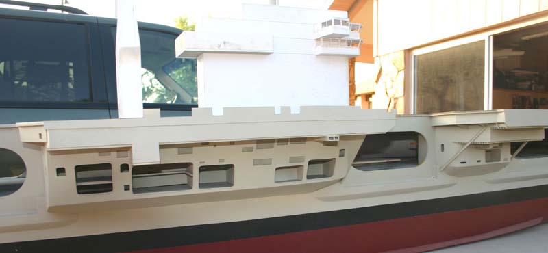
Here are some additional shoots of the Truman showing the starboard sponson
under the location for the Island. All of the recessed openings that have
decks have to be made and done before the outside covering can go on to the
model, do to the reasons that these areas may not be so easy to get to later.
I have figured that about 75- 80% of these decks need to be done before that
outside covering can go on.
October 20, 2006 Update - more progress on the sponsons


July 2, 2007 Update
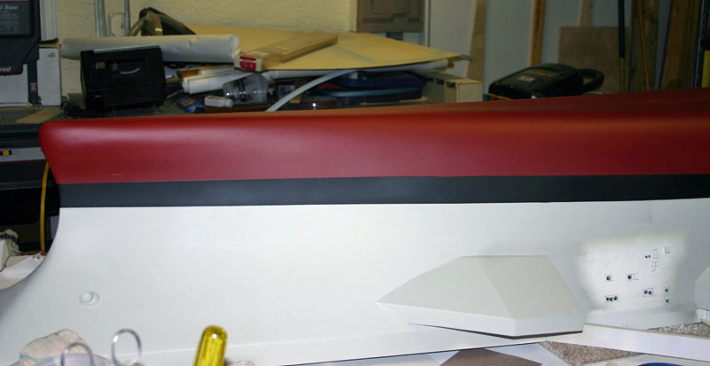
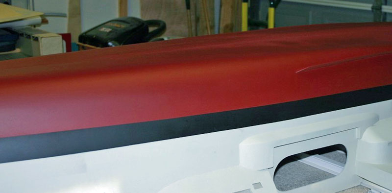
With hull turned upside I went ahead and painted the lower section from the boot line to keel.
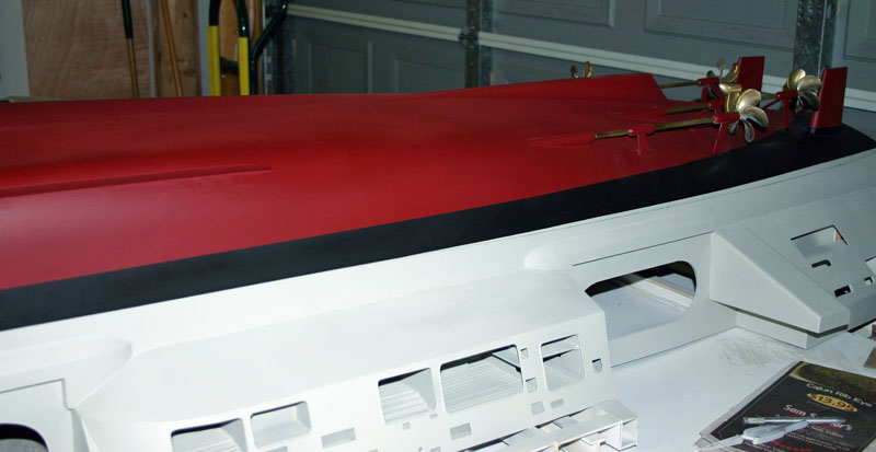
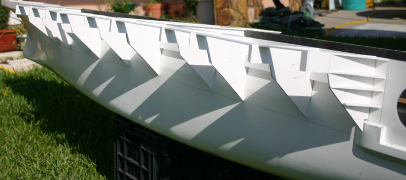
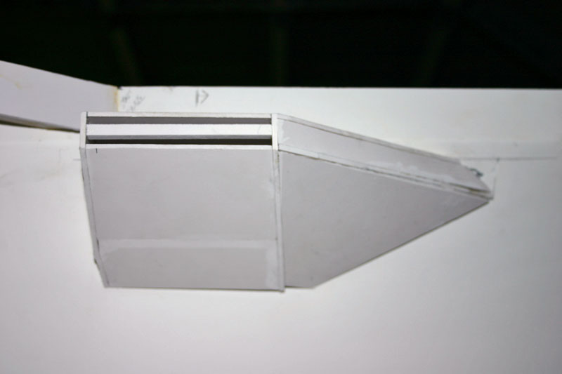
Beginnings of the sponson edge that are forward and aft of the elevators, this section is the forward edge of the #1 elevator.
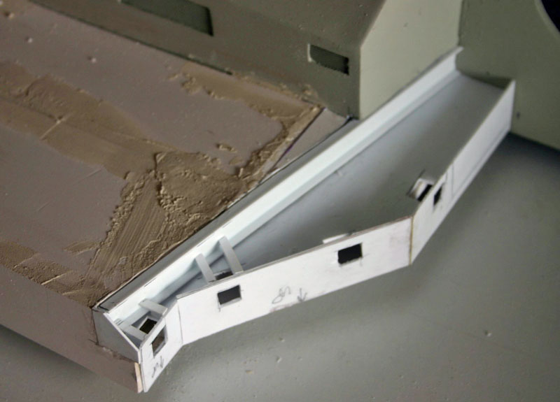
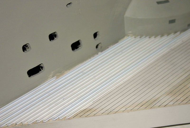
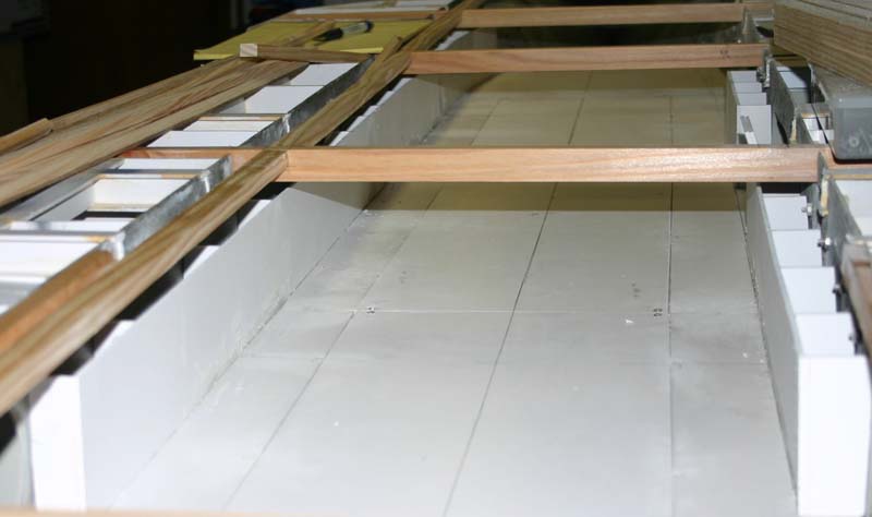
Start of the layout for the 1/8" I-beams that are located under the flat portions of the over hanging sponsons.

Yet another shoot showing the I-beams that are being installed.
Here you can see the overall area of were the elevator will be once in place. I have decided to make the #4 elevator in the raisedf position, so that means that the detail of the opening will not have to be cut in for they will not be seen.
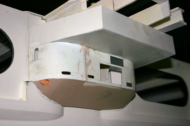
Aft starboard sponson is now starting to come together. This is one of three locations in which the Nato Seasparow launchers will be located.
Aft starboard sponson showing some of the openings that are located in this section.
You can see here that the decks within the aft sponson have been put in place along with the mesh screen for the vents that are also located here.
The #3 elevator opening in it's rough finishing with some work left to do to get it all smooth and ready for painting.
August 30, 2007 Update
Started the hanger bay from many photos that were obtained from the internet and with some help from two friends that served on these carriers.
Bulkheads going into place, now we are starting to look like a hanger now.
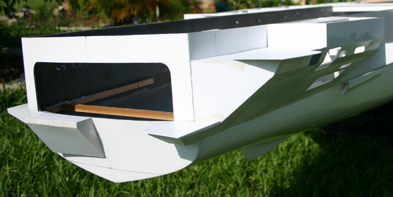
This was my first piece that I made that will gop on the stern of the CVN. This part of the section that they use to go onto liberty in a port in which the ship is anchored out and they bring a barge out to the ship and secure the barge at the stern of the ship.

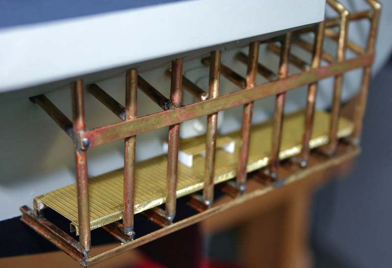
Here you can now see that most of the frame work has been done now with a few more parts to be made or fitted to give us more detail in this area of the ship.

Water tight door now inplace before the final place ment of the brass cage to the hull of the ship.
Brass cage fitted in for a test fit. I had to keep test fitting until all brass rod was just touching the hull to give it a nice final look that would pass with me.

Have placed a few more parts such as the mesh deck in its place along with the raised mesh deck near the hatch.
Now painted, still have a few more parts for detailing to go onto this section to give it that used look.
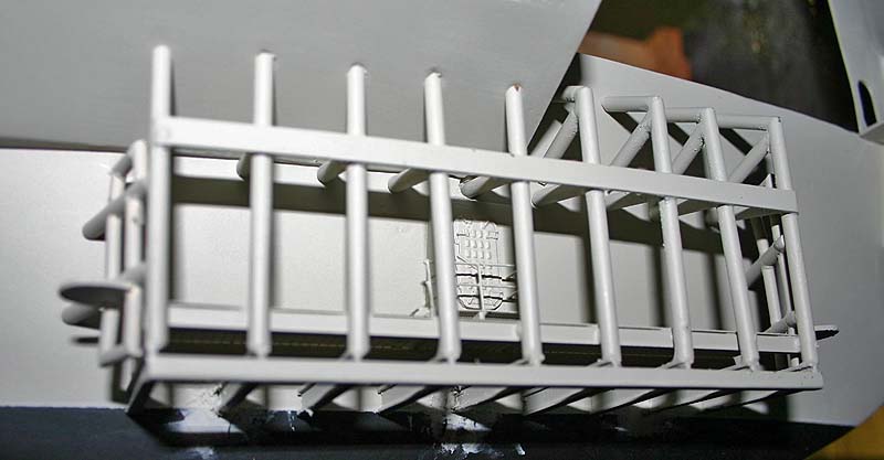
Another view in which you can see the one side showing the angeled section that had to be put in place, this is also made from brass and was a little trickey to get into place with out placing to much heat so that other sections would not de-solder and fall off.
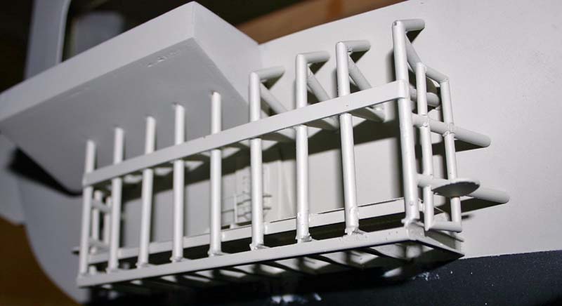
Once again stern view showing the liberty section along with the new part on the stbd side showing that of one of the twenty-four hull bitts that willl be placed onto the hull that willl be actually fuctional units.
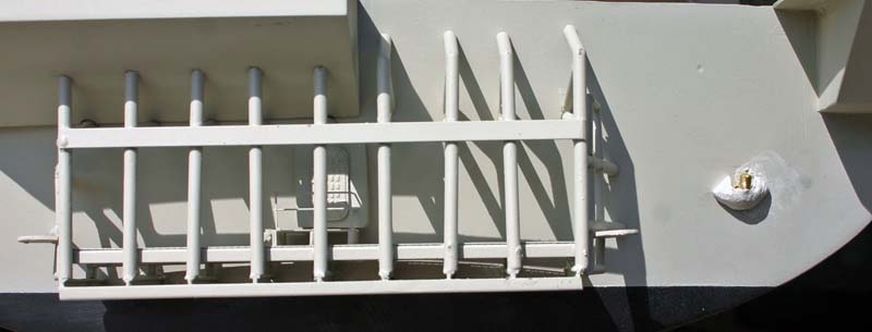
Close up of two of the hull mounted bitts to be placed onto the hull. Here you see in the side view that they are threaded and will go through a block of wood and will also be epoxied as well. Front view will show the general shape of each bitt.

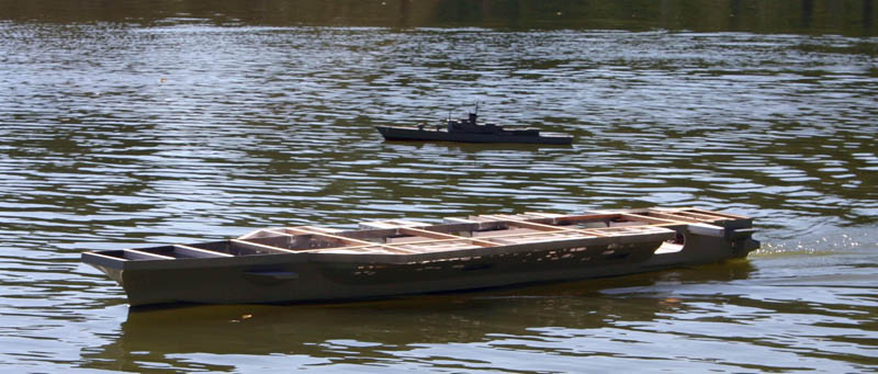
October 29, 2007 update -sea trials in North Carolina
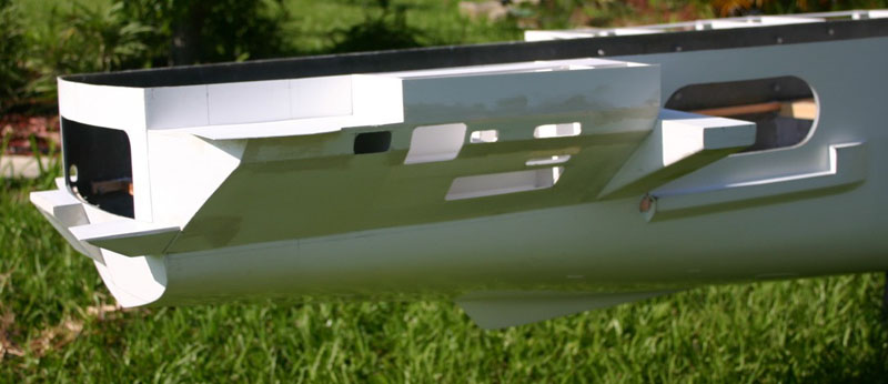
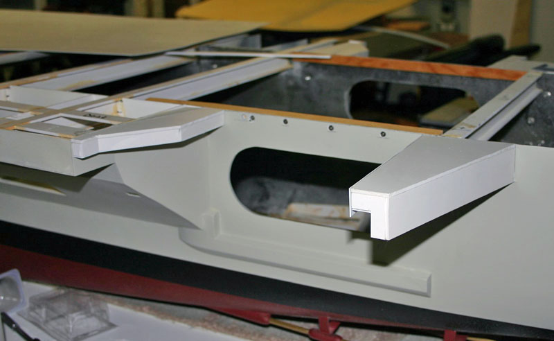
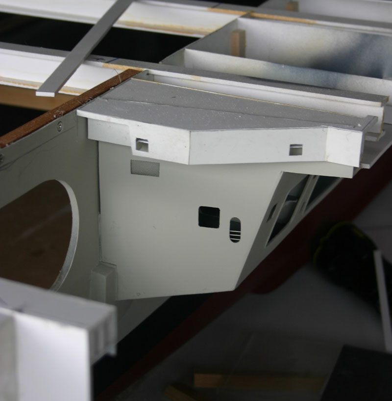
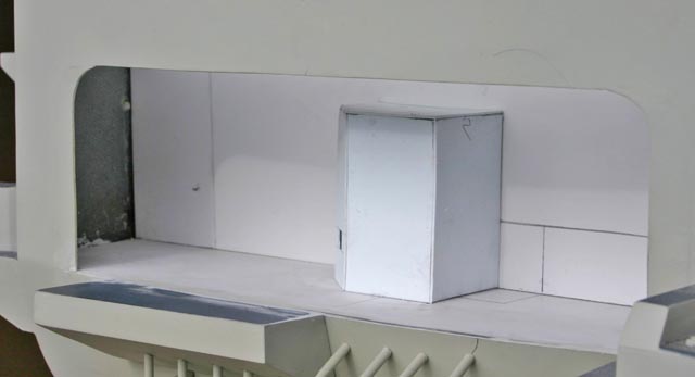
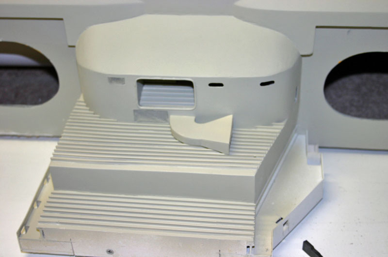
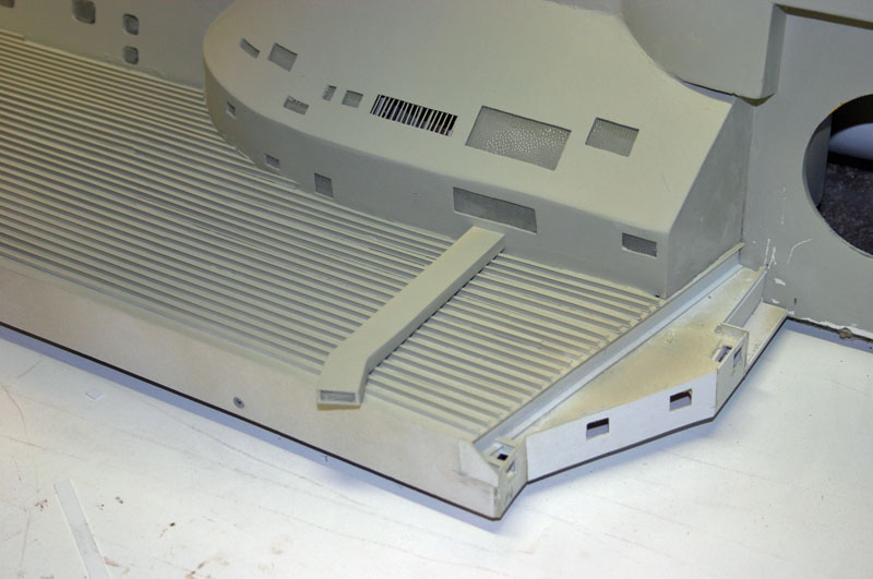
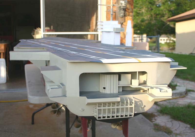
Started the stern deck of the ship where Jet engines are tested after they have been repaired.
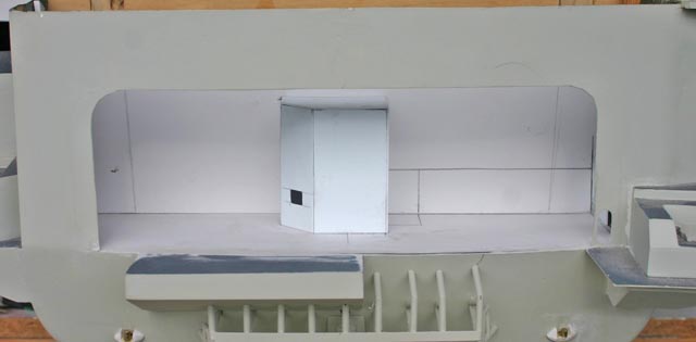
Different angle. Here you can see one of the bulkheads that have to be placed inside of this area. There is one opening in this bulkhead for a passage that goes down the stbd side to the hanger area.
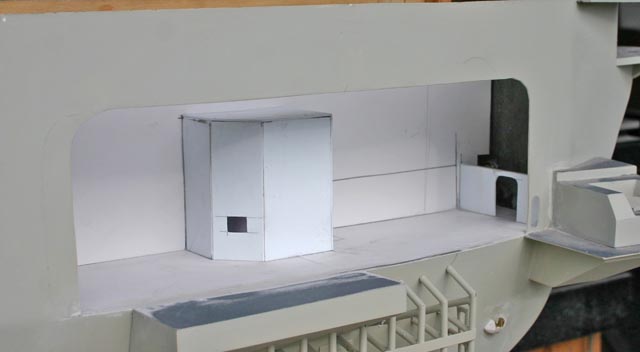
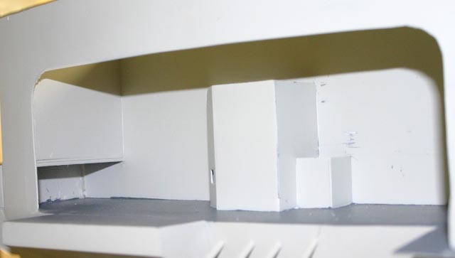
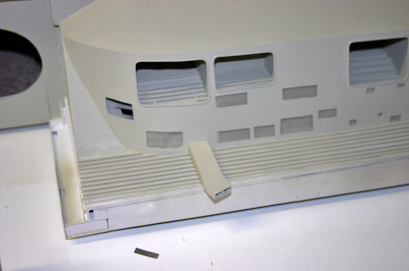
Opposite angle, bulkhead not inplace yet.
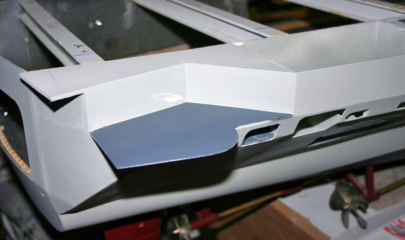
Bulkhead inplace, but as you can see it does not go all the way to the deck, there are 1/8" I -Beams located under the overhang.
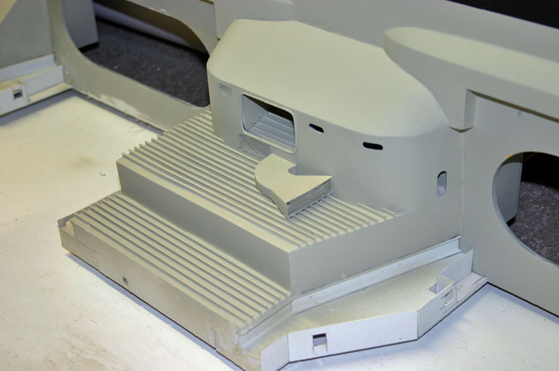
Overhead view showing the deck and bulkheads already inplace and painted, ready for the next step.
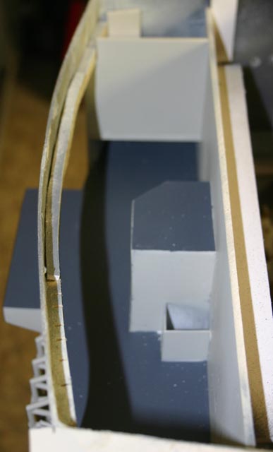
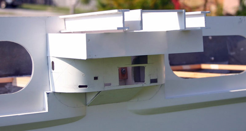
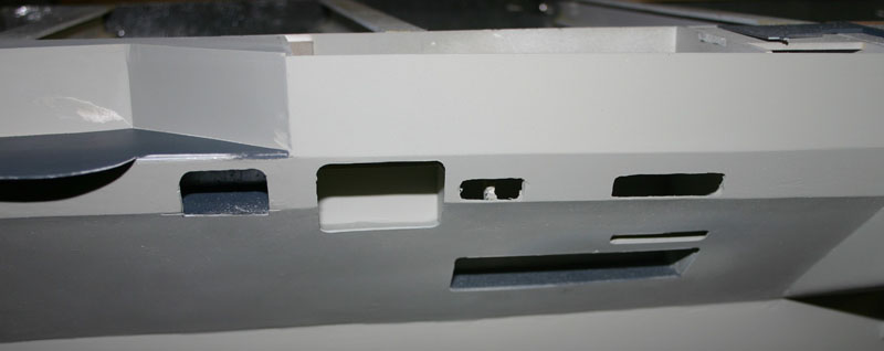
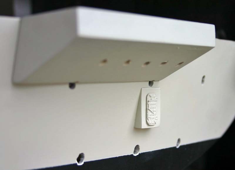
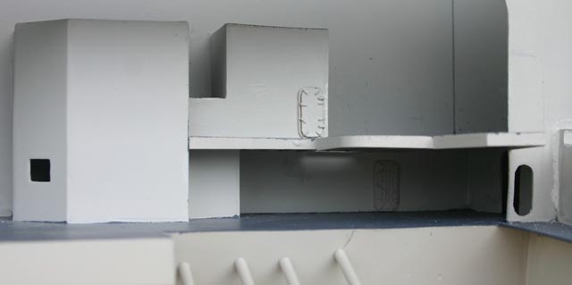
Now for a close up of just some of the detail to go inside of this area of the model. Now you can see I have built more structures inside and they were painted before they were placed insdie. Also the next deck level a large platform has been added.
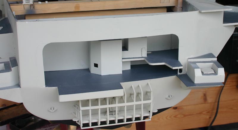
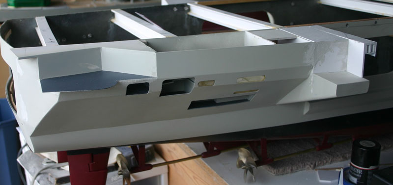
Same as the photo before just a different angle so that you can see the Water Tight door below the platform above. There is a lot more details to be built and placed into this area, just one small part of a very large build.
4/14/08 Update
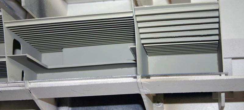
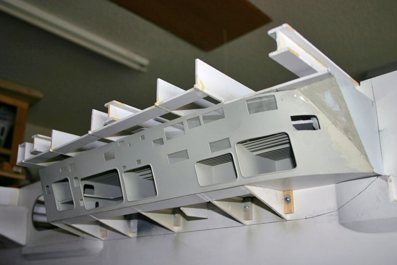
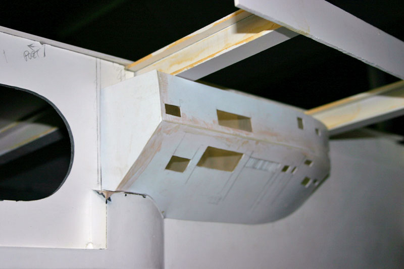
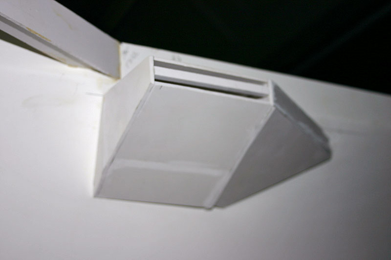
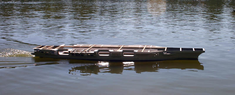
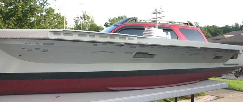
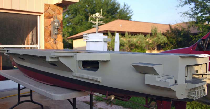
I finally got all of the I-beams in place that go underneath the over hang of the flight deck. I have now started and got the stbd side done with the vents built and placed into their location as on the real ship. I have also built the one structure section that hangs down from the overhang as well. The carrier has now got to the point in which I can no longer ask the wife to help move it around or to turn the model over to work on it. I have to get the neighbor to help with the turn over, as for just moving it around I have a small work bench I made at the same height as my big work bench that I slide the model onto for simple moves and for cleaning of the big bench.


July 19, 2008 Update
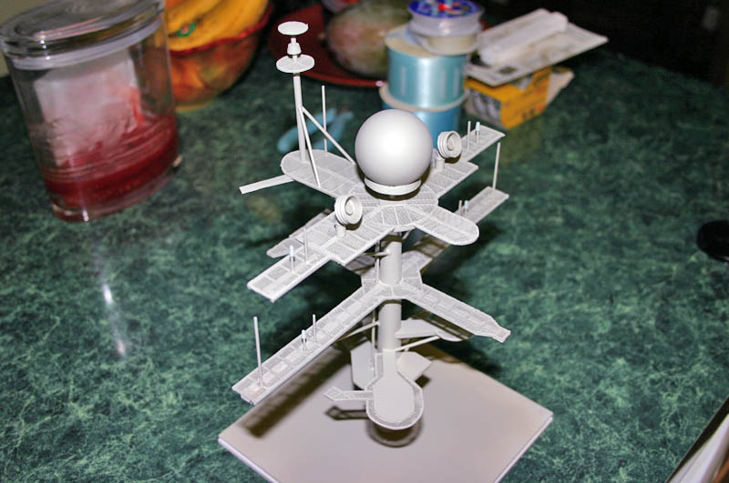
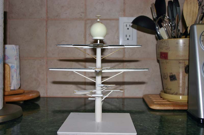
Working on the mast...
July 28, 2008 Update
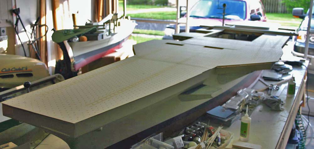
Flight deck is finally going onto the model, this process took me a couple of days to make sure that every thing stayed align, and I also had to do cut and remake a couple of areas.

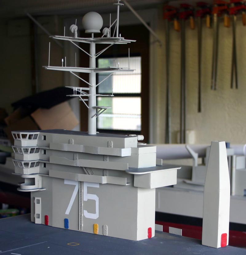
Start if the Island looking at the lower two bridge levels.

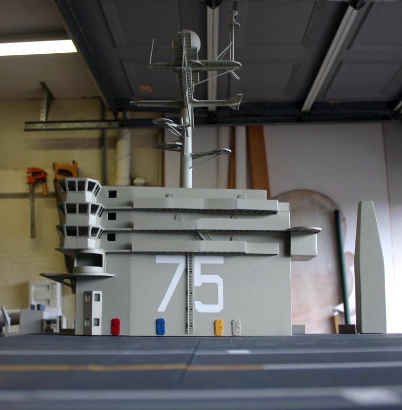
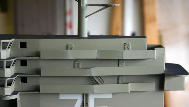
The Island is a little further along here, still have lots of work to be done to structure.
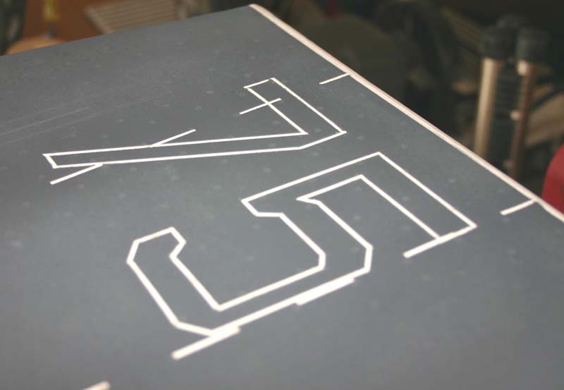
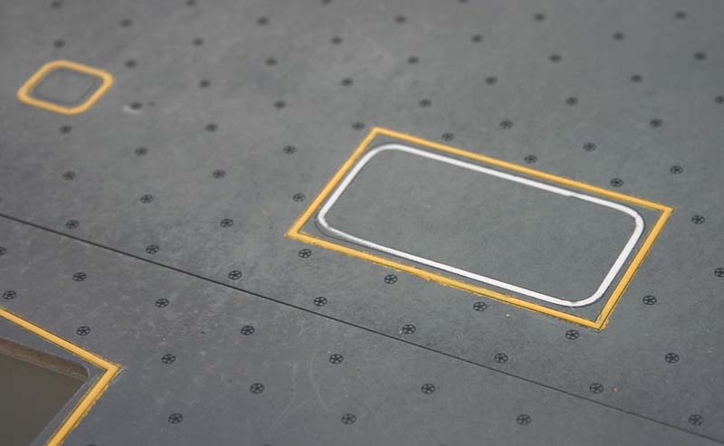
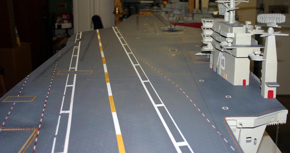
Deck is painted, here you can see some of the details and the ship's hull number on the bow.
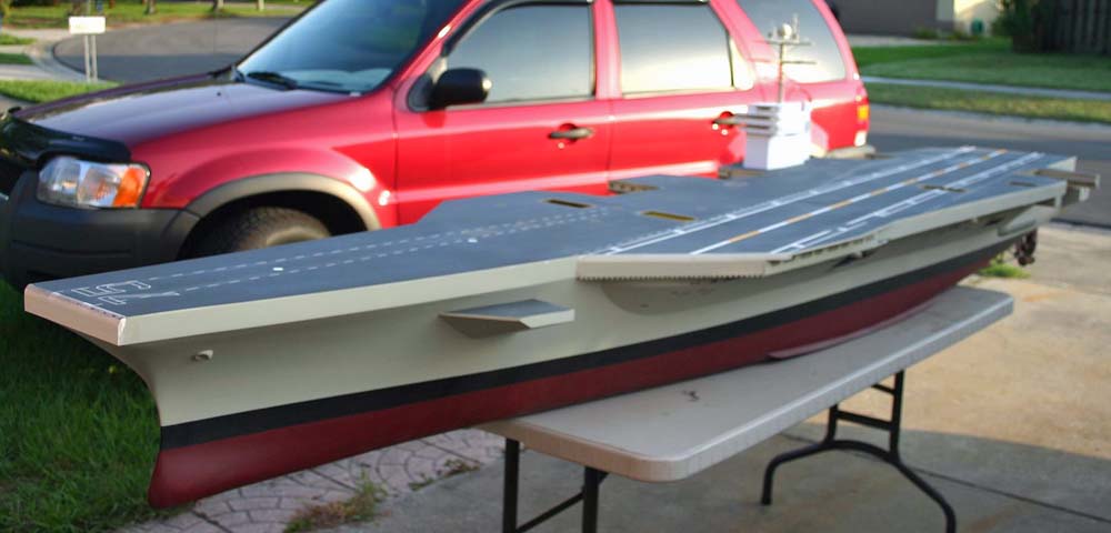


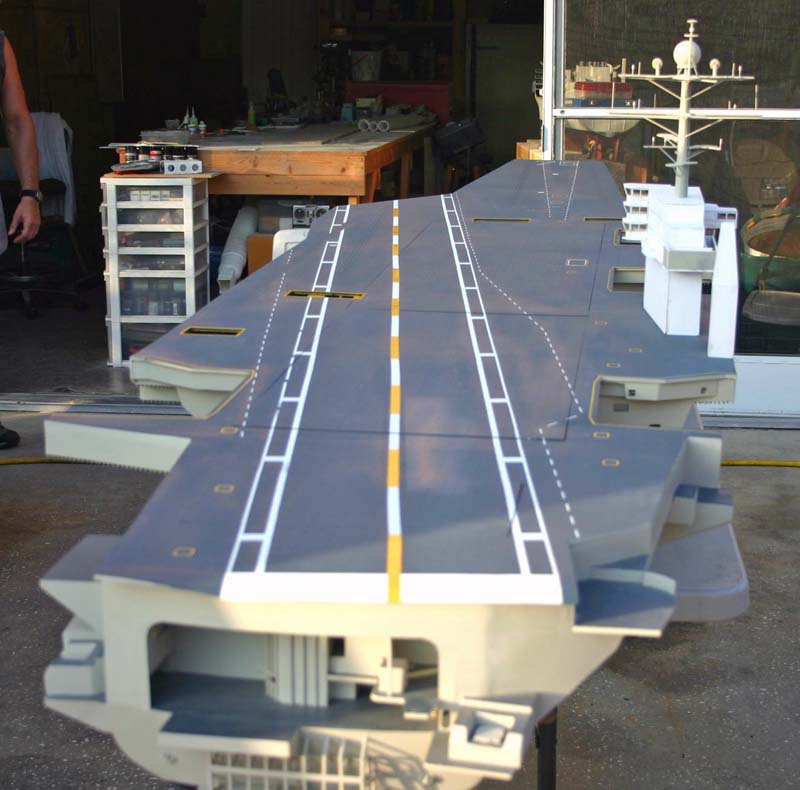

Over all views of the ship.
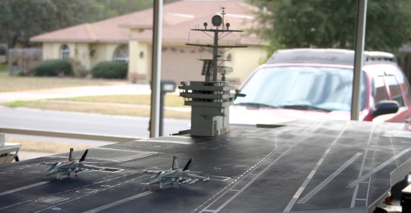
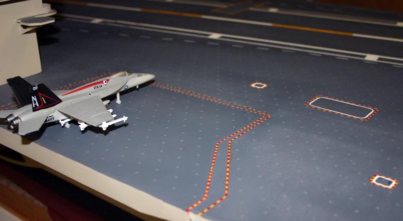
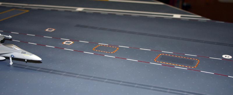
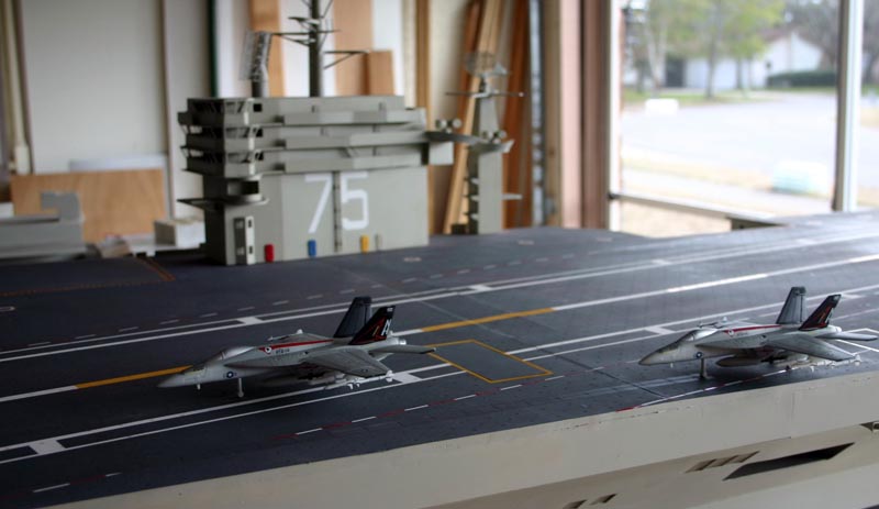
February 26, 2009 Update
Deck has warning stripes painted on, some more superstructure work, and the airwing has two new fighters.


![]()

Back to Warship Models Underway
This page maintained by Kurt Greiner. Email me here.
This page viewed 165
Version 1.295
Last update 12/09