


Click on any image that has a border to enlarge. -
Hello! I guess I should start with a little bit about me, my modeling experience, and why I am writing this. My name is Matt, and I'm currently attending Arizona State University here in Phoenix, Arizona. I'm returning to school after taking a few years off to work, and am finishing my senior year, hoping to start Law School in the fall of 2003. When I was a kid I built several plastic toy models, and always enjoyed it. Now that I'm older I have been looking for a new hobby and thought I might try R/C boat modeling. There is something I want everyone reading this to understand from the beginning, I have zero pervious R/C, scale or boat modeling experience. I am, and will be for a long time, a complete beginner, so when reading keep that in mind at all times! The reason I have decided to write about my success and failures during my first attempt at ship building is simple, I have had a hard time trying to find one place, store, website, book or kit that is for the complete novice. I have found several great resources (this website being the best by far, so book mark it!) but none that where geared toward the novice. Each had great info on specific topics, but none that really gave me a complete "feel" for what I was getting into, before I took the leap, and spent the cash.
That is what I hope to do here. Give someone who is thinking about getting into the R/C Scale modeling hobby an overview of what to expect. This is NOT meant to be a "how to" article in anyway. My intent is instead to give you a look into my experiences, trials, tribulations, thoughts, mistakes and successes. I plan to take a lot of pictures during my construction, and make comments about things I learn during the way. Again, even if you should buy the same kit I am building, DO NOT take this as a how to! To be honest I tend to cut corners sometimes. You see Math and I have an agreement, I hate it, and it hates me (hence Law School, that's about the only thing you can do if you hate math!). So I don't always get the correct measurements, I tend to be a sand that sucker until it fits kind of guy, rather than getting the correct length the first time. So how I build my model, and what I expect out of it may not be the same as you. I have decided this first attempt will be exactly that, my first attempt. I am not trying to make a museum quality ship here, I realize that there is no way I could with my current skills, and if I tried I would probably not be happy with the end result. Instead my intention is to get the kit built, running and in the water, with as much detail as I feel happy with. I'm not expecting to win any awards, or have the most realistic ship my first time out, instead I want to build something that I will enjoy during the process, will allow me to play with, and give me an outlet for getting my feet wet. This is a beginners project, and should be treated as such when reading this summery. That being said, lets get started!
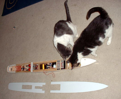
For my fist project I choose a "complete kit" form Deans Marine. It is a 1/96 scale USS Kidd, a Fletcher Class Destroyer from World War II. Although the box says it's a scale model of the USS Kidd the plans included are for the USS Fletcher. That is the neat thing about scale modeling I think, with one "kit" you can actually build any of the ships from that class. For the most part all of the 175 Fletcher Class Destroyers built were very similar, with only minor changes in armament, bridge layout and fittings through the line. That being the case, it is pretty easy to do your research and take the kit for the USS Kidd and turn it into another Fletcher Class ship. This is what I have chosen to do. I have decided to model my boat at the USS Stevens (DD 479). The Stevens was one of three Fletcher Class Destroyers modified to carry an OS2N-I Kingfisher floatplane on a catapult instead of the number 3, 5-inch gun during World War II. I chose this ship because it was unusual, and also the specific plans were readily available from The Floating Drydock . Here is a photo from the day I got it:
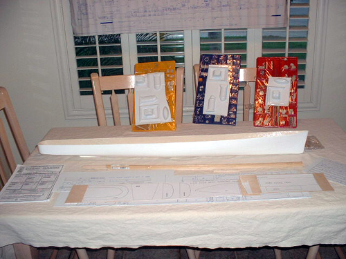
First a brief description of the kit. In the photo above you see everything that comes with it. The hull is in modeled fiberglass; the white sheets of plastic are exactly that, sheets of plastic with outlines printed on them to guide the cuts that form the superstructure. It is kind of like a jig saw puzzle if you will, all the parts that make up the "buildings" on the ship come as flat, but sturdy, pieces of plastic that must be cut, and glued together to form a 3-D model of the upper structures. It's really not as overwhelming as it sounds. Everything is labeled, and has a corresponding number on the plans; it is simply a process of putting the numbers together in order to build up the specific structure.
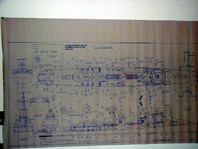
The Plans are the blueprints of the ship, and you can just see the bottom of them on the picture above taped to my kitchen window blinds. The plans are "in scale" meaning that when you measure 2 inches on the plan, it should equal two inches on your actual model. Or to think of it another way, if you do everything correct and hold your finished project up to the plans they should both be about the same size. I say about because you should always measure once, twice, three times with a good instrument to be sure (doesn't matter for me I always get a different result each time!. Being off one or two inches could really come back to haunt you latter! Measure, measure, and measure again. Also a hint I picked up from Roy on the Warship Models Underway (WMU from now on) forum, use the same place, line or point to take your measurements from. Always using the same spot should give you the same results each time. Here is a close up of the plans included with my kit:
Also included in my kit are "fittings". The best way I can describe fittings is all the little details that make a ship scale. For example; guns, watertight doors, depth charges, radar, railings, ship's bell, these are all considered "fittings". The fittings are scaled to the ship for this kit, 1/96. Which by the way means that 1/8th of an inch on the model, or plans, is equal to 1 foot on the real ship (1/8 inch being 1/96 of a foot). Everything on the ship and plans is scaled down to that size, but hypothetically if you blow the ship up once you where finished, everything would be the same size on your model as it is on the real ship. This is important because this is a scale model, it's meant to look as much like the real ship, only in miniature, as it can. There are over 200 fittings with is kit. They are divided into plastic bins, of different color.
Hint: once you get a kit, check the parts sheet against any bins you might have, so you know which is which. I looked for things I recognized in each colored bin, propeller, rudder ect, and then colored the top of the parts list in the instructions with the same color. Each list was on it's own page in my kit, so it was easy to do. Now when I need to find a part I look it up on the list, check the color at the top of that page, then grab the corresponding colored bin). Here is a pic of one of the fittings trays:

It looks overwhelming, and to be honest it is, but I'll talk about that at the end of this section. As you can see, if you're not an expert, and I'm not,on naval fittings it is good to keep your parts list handy (and color coded) for quick reference.
Hint: cut open the plastic covering the individual squares with an exacto or hobby knife only as you need them, that way the other parts are still covered in case one of your cats decides to knock it off the dining room table! DOH!
As you might have noticed in the overview there are also some white plastic 3-D moldings. These will become the turrets, smoke stacks, and lifeboats. This type of molding is known as "vacuum forming". The best way I can describe them is that they are of the same consistency as packing plastic, or the plastic that you have left after you eat all the chocolates out of the valentine you where going to give your girlfriend/wife/significant other/pet whomever. Yes, its about that flimsy, I could easily crush one of my turrets like King Kong if not paying attention to what I was picking the finished boat up with. Personally, so far, this is the only part of the kit I'm not happy with. To me they are just too flimsy, and me too big of an oaf to safely use them. You may be completely happy with them, but if not luckily you can find LOTS of fittings in 1/96 scale and just buy ready-made turrets or lifeboats in the $15-30 range (each). Again this is a personal choice issue, some of you may be completely happy with what comes with the kit. Another option is you could scratch build them yourself out of balsa, sheet plastic, or whatever I suppose. "Scratch building" is exactly that, you take something like a block of balsa and cut, carve, and shape it until it looks like the piece you are trying to build from the plans. I am going to try to stay away from scratch building as much as I can on my first project.
Lastly I also got several other parts with the kit, mainly some balsa wood strips, ramin wood strips, propellers, propeller shaft, rudder, instruction book, brass wire, and some extra plastic sheeting. That is basically it for the "complete kit". I think this takes some explaining here, for those like me looking for a "complete kit" to build. Kits can come in many forms, hull only, hull and drawings only, semi-kit (I've seen these as hull, drawings, and running gear, which means prop shafts and propeller/rudder), or complete kits which usually have all of the above, plus the fittings and an instruction booklet. Every manufacturer is different, so make sure you really study what comes with your "kit" before you order it, so you know what all you are really getting and are prepared to buy or make what you are not.
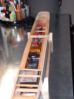
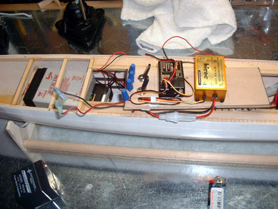
Now, that's everything I need to put my ship together, well except adhesives and glues (which I will cover later after I have tried some different types). But it does not include anything to make it a radio-controlled model. You still need to get those items as well. This can be a bit confusing, so I'll relay what I have learned so far. You will at least need a motor, radio, and a battery. I suggest buying them early in the building process, if not actually when you get the model. The reason being is you have to start putting these things in rather early in the construction (like 2nd or 3rd step in my kit) and you need to make sure they fit before you start adding supports around them, and decking above. Here is a good picture to illustrate what I mean. My hull is complexly empty right now, no supports or decking, but you can see one (this kit takes 2) of the motors, a servo (explained later), a ruler and a fork (hey it's for scale OK, also good for mixing glues w/ the handle).
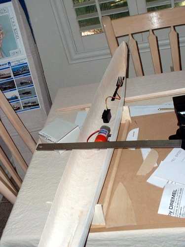
As you can see, it will start to get very crowded in there soon enough. Without the having the motors and accessories on hand to measure, I might build myself out of an R/C boat. So I bought these with the kit from the same retailer.
Ok, what I have learned about R/C radios so far. The Radio is actually more than just the control box with little sticks that we have all seen before. The radio consists of:
1. The Transmitter or TX; this is the part you hold in your hands and use to control the way the ship moves, or how fast it goes.
2. A Receiver, or RX, this is a small box you put in the boat that "receives" the imputes you are "transmitting". It then takes these directions and coverts them into signals that it sends to...
3. The Servos. The servo is another small black box, with either a wheel or arm on top. The servo takes a signal from the receiver and turns into an action, such as turning the rudder. All of these items should come with most radios as a set. Check with whomever you are buying your radio from, to determine what comes with it. Radios come in deferent frequencies, the primary radio frequency for ground R/C in the US (includes cars and boats) is 75 mhz. Again check with your retailer to find out what is legal in your Country. Radios come designated as 2 channel, 3 channel, ect. I have seen them all the way up to 9 channel on the web, probably even more. The thing that is confusing to me, and others starting out I bet, is that channels are not channels at all. A two-channel radio operates only on 75 mhz, not two "channels". What a "2 channel" radio actually means it is has two FUNCTIONS, for example one stick controls the speed (Channel 1) and the other stick controls the rudder (Channel 2). As you add more "channels" (functions) you can control more stuff, like lights, a pump, or even sounds.
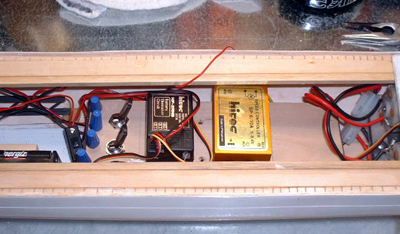
This is a very basic overview of radios, and their functions, it is not meant as a "how to" , but only to give you a brief overview and vocabulary so you can follow along when you talk to a knowledgeable retailer. If you want to learn more, I highly recommend a book called The Complete Marine Radio Control Manual by Hugh Bright, it's great book and explains everything about radios in a way you can understand, as well as the specific details you will need to know as you get more advanced. To wrap up you only need a basic two channel to make the boat functional though, one to go left and right and one for forward and reverse. I got a two channel radio for this kit, it's basic but it will handle the two functions my boat needs. Here is a pic of the radio I got and all that came with it:
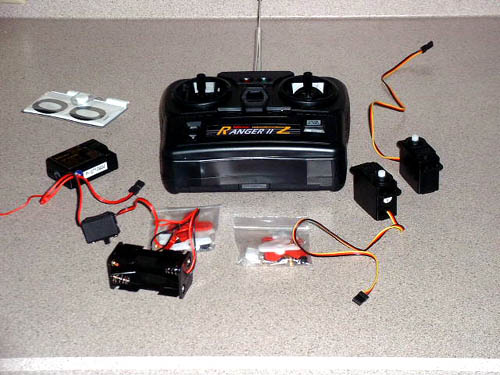
As you can see it comes with the controller (Transmitter), two small servos (on the left) and "arms" for the servos in little bags (several different types) a receiver (small box on left top) and a battery pack for the receiver. Also included is a "frequency flag" that you put on your antenna at the pond so others know what frequency your on. This is because more than one person cannnot use the same frequency (the 75 mhz band has a number of frequencies which range from 75.410 to 75.990). If you and another boater at the same pond are both using 75.410 mhz bad things will happen, so know your frequency and wear your flag! Again talk to your retailer about this when buying your radio for more details and options.
You will still need a few other items to get your boat moving, but most of this depends on your "kit" you are building. For example you still need:
1. At least one motor (my kit takes two)
2. At least one battery, 6v to 12v are the most common voltage from what I have seen (and will need to match your motors and other electronics to this voltage).
3. Couplings to connect your motor to your engines.
4. Linkage to connect your servo to the rudder tiller
5. A Speed controller to go from the receiver to your motor(s) to control the speed at which your boats goes through the water. I will not go into detail on these items, as I do not know a lot about them at this stage. Instead I would recommend that when you talk to your retailer you discuss these items, how they will relate to your specific kit and what you will need so they all work together nicely. Most retailers can recommend a radio and all the devices that will work with your particular kit, and that is exactly what I did when I bought mine. Like I said before, you might want to get everything at once, that way you know they should all fit and work together!
So, what does all this cost? Well I am sure there are as many different ways to build ships as there are types to model. Your costs could vary from just a small initial investment, to buying the best of everything. For my kit I spent $699.00 for everything listed above except a battery and adhesives, and that included shipping. Now knowing what I do know, would I have done the same thing again? No. This kit is just too big for a beginner. Don't get me wrong, it's a great kit, but overwhelming for somebody like me with zero previous experience. If I were starting over I would buy something smaller (not scale wise, but sheer number of parts wise, I might even go to a larger scale to give me more room in the hull to put things) and less detailed for my first model. That way I could spend less time building and get it into the water quicker. A lot of people have told me the sooner you get it into the water, the better. Fewer parts, fewer engines would make that a reality quicker. If I was going to do it over I think I would start with a larger scale Tug, or PT Boat first, rather than a large complete and detailed kit like I did. The other thing I am now learning is that the radio I purchased (2 Channels) is rather limited. If I want to add more functions, such as working lights or sounds later, I will have to purchase a four-channel radio to control them. That means I will have to replace at least the receiver I have already installed in my boat with that of the newer radio. I think that if I was doing it all over again, and could afford the extra $100 bucks for a four-channel radio I would, that way I could control more functions in the future if I wanted too.
Well I hope that if you are new to R/C boating and modeling like I am I have managed to answer some basic questions for you, and arm you with some vocabulary so that you can start your search for the right "kit" for your individual tastes. I know I wish I had this knowledge before I bought mine, so at least I would know some of the later question I had to ask the great folks on WMU. Do your research, see what you like and talk to people here and retailers on the net or in your area about the kits they sell, radios, motors and batteries before you buy, that way you are much more likely to make an informed and educated decision and end up with a successful and fun modeling project!
The first step in my directions was to prepare the hull. What I needed to do here was sand. I sanded the top edge of the hull with fine grain sandpaper to get any clumps or drips off, and to even them up to my eye. Do this outside in a well ventilated area, as the fiberglass dust is not good to inhale. Then I sanded the bottom until the six round pour marks left in the hull from the mold were blended in as much as possible. Next I was told to sand the interior to a "smooth" finish, and add a light "filler" if needed. Filler is kind of like a cr�me paste, it's comes out as the consistency of toothpaste, can be spread with a spatula, and dries to a hard sand able finish. I could not get a "smooth finish" using sandpaper alone, so I thought I would add the filler, big mistake. The filler I first bought was called MicroLight, and by shear dumb luck was water based. After I had coated the entire inside of the hull, I realized A) any water in here would melt the stuff; B) it was not strong enough to hold a glued item to the hull. After asking what I should do on the WMU forum, I found out all I really needed to do in the first place was sand the interior to rough it up enough to get a good "key" (surface) to glue to. So I spent the rest of the day hosing out the filler, what a waste of time and money!
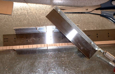
The next step was to drill out the prop exits in the hull. There were two molded in prop exits, along with a spot to drill out the rudder hole. I took a drill bit small enough to fit in-between the mould marks, yet large enough to get a small rifle file into. A rifle file is a round, square or flat file used to make holes larger, I bought a set for about 12 bucks. Once I had the holes drilled I had to use varying sizes of rifle files until I had the entire area of the prop exits filed out and as square as I could get them with the naked eye.

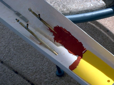
This photo, albeit blurry, shows the finished holes for the props and rudder. Here I have the prop taped while measuring against the directions and plan to see if I have it set right. Once my measurements matched those on the plan I used a little bit of super glue to tack the prop into place, then proceeded to do the same with the next one. After tacking into place I added shims under the shafts inside the hull to help support them. This was done with scrap balsa from a bag of different balsa shapes I bought at the hobby store for about 6 dollars ( A BEST BUY, I use something from this bag almost daily!). Once both were secure, it was time to seal the holes.
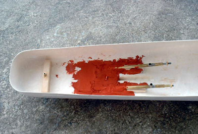
Here you can see the shims, and that I have used another type of filler to waterproof the hull. I could not find the brand Evercoat, which Kurt recommends in my area, but used a glazing and spot putty I found at my local auto parts shop. (Editors note, Evercoat is available from Automotive Paint supply stores, or over the Internet, see the Working With Catalyzed Putties article on this site for sources.) This stuff has the same consistency as the water based filler described above, but is both stronger, and water proof. The down side is it stinks bad, use only in well-ventilated areas, like outside! The stuff is also rather toxic, so be sure to follow the manufacturers instructions for safety to the letter, and wear plastic gloves. I used a disposable plastic spreader and a small metal spatula to get the stuff into all the corners. While I did not realize it at the time, I could have just used it inside and still sealed the hull, but instead I applied it to both sides of the opening. I also used too much, this stuff ads weight, and does not need to be as thick as I made it. (Editors note: if you do use laquer based spot putty, be sure to apply in multiple thin coats, as it can take days to harden in thick coats, and may crack) I then left it over night to dry in the garage. (Even after I applied the product it still stunk for about 2 days, so I kept my model outside until the smell went away.)
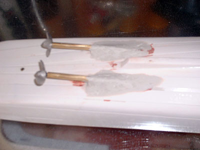
This pic shows the spot putty ready for sanding. As I said before I put too much on! I sanded it down to a smoother finish, for looks more than anything else. Also overnight small cracks had developed, probably from me going out every couple of hours and pushing on it to see "is it dry yet?" J Here you can also see the rudder hole and a piece of wood used to strengthen it. This was recommended to me on the WMU forum as well. All I did was take a piece of scrap wood (not balsa, too soft) and drilled a hole into it. I then rifled it out until the brass tube the rudder would sit in could fit through the hole. Once I was satisfied it fit, I tacked the wood to the hull with super glue, then a small bit of the putty around the inside of the wood, none on the outside of the hull, I learned that lesson! This added extra strength to the rudder assembly in case I hit something hard underwater like a whale or a shark.
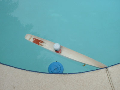
After sanding everything I decided it was time for a leak check. I placed the model in my pool, with a heavy can inside to force it down in the water and checked for leaks. Non-detected, luckily I have a pool, so this is easy to do, if not you could use your bathtub as well.
Finally here is a picture of the underside of the hull, and my final finishing. The red spot putty had a few cracks in it, and while not leaking, did not look that great. Here I used a different spot putty, this time white, to create flares around the prop shaft. While not in the plans, no propeller struts (outside supports that the props go through) were included with the kit, so I made the mounds you see with this putty, again sanding as smooth as possible for looks and drag created by a rough surface.
Mechanicals, support beams and electronics.
Now that I have the hull prepared it was time to start getting the R/C equipment in place and installing the beams and cross members that would give the hull enough strength, both on the water and while being moved around the shop.
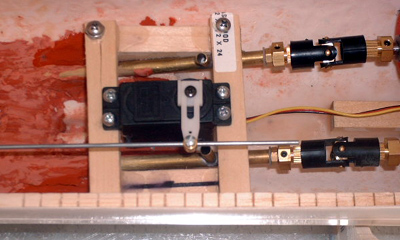
I first started with the servo that would control the movement of the rudder. From research and talking with folks from this website I determined that the servo should be placed as close to the rudder tiller as possible. This would allow for a shorter run between the two, and less chance of binding, or getting into the way of other items in the hull. For mounting I used some scrap basswood measuring 1/2x1/2 that I picked up at the local hobby store. I drilled holes matching those on the servo in these beams and secured them with screws and nuts. It's a good idea to make these removable so they can be replaced should they fail in the future, as a RC ship without rudder control would not be much fun. After that was done I trimmed the servo mounting beams to fit, and glued additional beams on the sides of the hull to mount my cross beams on. These do not need to be removable, as I can just unscrew the servo to replace it.

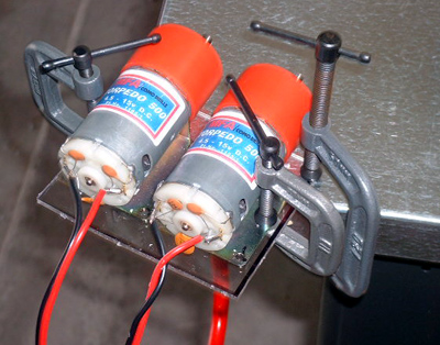
Next I began work on a mount for my two motors. These also needed to be removable for replacement , but also must have a sturdy connection to the hull to prevent movement. Again I got a lot of advice, with Kurt and Roy providing some really good info. The hardest part for me was coming up with the actual design for the mount. Later I found that these are commercial available! (As are plastic servo trays DOH!) Anyway, I finally settled on a strip of 1/2x1/2x7 inch basswood secured to the center of the hull. I then placed threaded t-nuts into it to allow me to mount or dismount my motor tray. The motor tray it's self was formed from Plexiglas I purchased from a local glass shop (also available in most hardware stores). I then cut it with a scroll saw and marked the mounting holes located on my motors and dilled those and two center holes to match my basswood strip.

Here you can see the T-nuts mounted into the basswood . I used small washers above the Plexiglas to hold it down, and small rubber grommets between the plexi and the base wood to help with any vibrations. Also note the arrow on one motor, this is to remind me that this one needs to turn counterclockwise (the other clockwise), and thus wired backwards, to have both props running in the correctly.

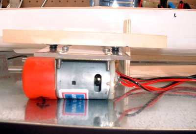
Here you can see the progression of the design. In the last photo it appears as though there is a vertical piece of plywood running through the motor mount, this is an optical illusion though, it's actually part of the stand to support my hull in the background. I did not catch this until just now; hope it's not confusing!
Some notes about using Plexiglas:
1) It has one great advantage, you can see through it! Helps a lot when trying to get those screws into the t-nuts.
2) It can let off some dangerous fumes when cutting or sanding with power tools, talk to someone knowledgeable about precautions you should take.
3) It's rather expensive compared to wood, I bought 24x24 sheet in 1/8", and plan on only using it in small sections at this time.
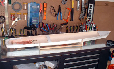
After I had test fitted my servo and motor mounts in the hull it was time to start on the deck and hull supports. I used the materials that came with the kit here, balsa for the deck supports and ramin wood for the cross members. I also used more scrap basswood to add strength.
For the deck supports I cut small "slices" about � of the way through the balsa with my hobby saw. (ED: This is also known as "kerfing") The reason for this is to allow the wood to form around curves and not distort the hull when securing. A good over view of this process can be found in the "how to" section of this website. Of course I did not measure precisely the distance between the cuts as you can see, instead I just eyeballed them.
The kit also included some plywood shapes for the bow, amidships and stern which I cut out and sanded to fit. Once I had all the deck supports ready it was time to install them. For this I took another tip from the "how to" pages here and created a "deck depth" jig. This allowed me to run it down the length of the hull and set the deck supports at the correct height so that when the deck is installed it sits flush with the hull.
This view shows the plywood shapes installed as per the plan. It also shows my first mistake in this process. The amidships cross support is installed too far back. I relied on the cut outs in the deck when placing this, because on the plan it has this piece crossing over the middle of the main opening for access through the deck and into the hull.
This picture is a close up of the deck supports installed. You can clearly see the cuts I made in the balsa wood.
Here is an overview with all deck supports and cross members installed. I followed the plans for spacing here, but notice the thickness of the side members in the areas that will be open for deck access. Here the plan called for two lengthwise deck supports on each side of the opening, with � inch supports spaced every 1/3 inch along the run. There was no way I was going to be able to cut that many pieces, that small and have them all fit correctly. I decided to take some scrap basswood and trim, and then sand it to fit the area, and add support. (Unfortunately this also added some extra weight).
This might be a good time to talk about adhesives. There is a lot of discussion on what adheres well to what materials (ie. Plastic to wood, wood to fiberglass ect.). So far personally I have used primarily CA glue (Superglue) to attach just about everything. It is easy for me to work with, and has made a pretty strong bond between wood and wood, and wood and fiberglass. I have tested it, and even supported 5 pounds on a wood/fiberglass connection. Because of it's ease of use, inexpensive price, and ready availability I have chosen to work with it most often. I prefer using the Medium and Thick varieties. The Medium sets up fast, so it's good for items you have already clamped into place. The Thick gives you a few moments more to make any last minuet adjustments. I have stayed away as much as possible from using "CA Kickers" (this is an aerosol spray that causes the glue to set immediately, I only use it to "tack" items in place before securing them) because I'm not sure if it has the same strength as the CA allowed to dry naturally. There are a lot of adhesives out there, some made for specific uses, like wood to wood or wood to metal, and you can get more information on what types work best on the forum here.
Ok, after I had the deck supports and cross members installed it was time to get the mechanicals and electrical equipment secured in the hull. It is recommended that you do this after the supports are installed in case the hull shape is changed which could cause this equipment to no longer be line up correctly. It is a bit harder to do with all the beams in the way, but if you have already designed, built and measured for your mounts it's a lot easier. And if your wondering, yes my measurements were off, although only slightly, I'm getting better!
Once the mounts had been secured I needed to design a box to hold my battery correctly. The battery I'm using is a Sealed Lead Acid (SLA) battery. It is 6 volts, with 4 amp hours of power. This means it can basically provide 1amp for 4 hours, or 4amps for 1 hour. Batteries can be pretty confusing, and I recommend asking any and all questions you have on the forum here, nothing is too "basic" believe me, and you'll get lots of help form the folks that visit the board. I choose the SLA type battery because that seems to be what most people recommend, and they are easily available in my town. They cost between $15-25 for the size I have. You will also need to purchase a battery charger, this I did at the time I bought the battery to be sure they would work together. The SLA's are heavy, but can make up a majority of your ballast in many cases. Mine weights in at 1 pound.
For the mount I took a piece of scrap plywood and secured it level with the bottom of the hull. I then added a crossbar forward of the battery to keep it from being pushed any farther forward. I also added two Plastruc brand beams on either side on the battery box for to prevent lateral movement. I choose these plastic beams because I wanted to see what it was like to work with them for future reference, anything could be used here. Finally I added industrial strength Velcro to the bottom the battery and the top of the tray. It's a tight fit, but the battery is not going to move during use and cause the ship to list.
I then wanted to get an idea on what my run time would be with this battery. I want to set a cut off time for running that will allow me to get my ship back to the edge on the pond with plenty of run time left for any errors. My goal was 1.25 hours of run time off of my drive battery (this only being the battery that runs the motors, not the RX batteries). To do this I had to figure out how many amps my motors where pulling. This required a multimeter and some instructions from those more skilled than I. Kurt, the Webmaster of this site, was extremely helpful in this process. Although I actually had a multimeter, I had never used it, and can't even remember when I bought it. With Kurt's permission I have included excerpts from our e-mail conversations on how to figure this out. He provides easy to follow directions, and using this I was able to do it my first try:
"I think that if your motors are not real hot, you should be able to achieve that run time with that battery. Without the amperage and draw readings off the model I cannot tell you exactly. If you have access to a multi meter with a 10 amp input I can tell you how to calculate your running time. (Most better quality mm have this input)
To measure amperage, you attach your meter in series in your circuit. Put the black common or negative lead from the meter on the negative post of the battery. Make sure your meter switch is set to the 10A setting. Plug your red lead into the 10A-unfused socket on the meter, and attach that to one side of the motor. Run a jumper from the other side of the motor to the positive side of the battery. You will then get a reading while the motor is running.
Because this is an unfused circuit in your meter, there is some risk if you do this technique with very high amperage race motors that draw over 10 amps. Your destroyer motors should not fall into the category, at least without the load of the shaft and props on them. They should draw 1 amp or less free running in air.
You can use this technique to measure the actual load on the motor after you hook them to the shafts and props. Just place the model in your bath tub and take a reading while the model is running full speed against the side. Both motors should read very close to each other in amperage. By adding these numbers together, you can arrive at a total load for the model, which you divide into battery capacity to give you running time."
The reading I got was about .850 ish on one, and .799 ish on there other (1.0 would be 1amp, so both were drawing less than 1amp). From this I was able to divide the results into my 4amp battery determining that I would have enough power to reach my 1.25 hours of run time, with extra left over for any calculation errors. If you are like me and not sure why the reading as different for otherwise identical motors, the answer most likely lies in that one is "binding" slightly more than the other, probably because it is out of alignment slightly.
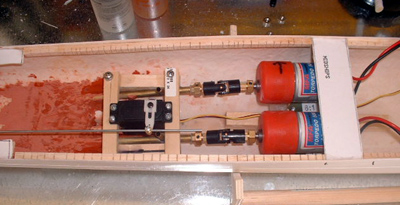
Here you can see the couplings that connect the motors to the shafts. The shop I purchased my kit from recommended these. I'm glad I got them because they allow a little more error on lining up the motors and the shafts. They also move in and out, secured by a hex nut, allowing me to back the motors out for removal once the deck goes on.
Now that everything was in and secured it was time to check the weight and waterline. To mark the waterline on the hull it is easiest to use a tool designed specifically for that task. Examples of what one looks like can be seen on the "how to" pages. Luckily for me Roy from the forum was nice enough to bring his waterline tool over and help me get the measurements. The key is to make sure the hull is level, side to side, and front to rear before marking the waterline. (ED note: Not all ships have a waterline that is parallel with the keel, be sure to consult your plans; one common example are Iowa class battleships) Once I had the waterline drawn onto the hull (measuring from the plans provided with the kit) it was time to get it into the water. I used my pool, but a tub would work just as well. It sat just below the line, with a slight list to starboard that I will have to ballast for latter, most likely using fishing weights. After the water test I used a bathroom scale to get the current weight. To heavy or to light, and the ship will not sit on the waterline, thus affecting its performance in the water. I made sure the scale was correct by zeroing in using something I knew weighted exactly one pound. The weight at this point was just under 5lbs. The kit lists the completed weight as 8.14 lbs.
If your kit does not include weight on the box, there are other ways to formulate it. Roy was nice enough to share these formulas with me. To get your weight range for your model take:
[Length x beam x (beam/2)] divided by ( BTW / = divided by) 100 x 2000 = pounds
Or
Actual displacement (of the real ship, if you know it) / scale / scale /scale x 2000 = pounds
So using this formula I could figure out the DRY weight of my ship. The dry weight is what it weighted in the shipyard with out ammo, people and supplies, not war weight. So this will give me a minim, and the box weight the maximum. So:
Fletcher Class destroyers had a displacement of 2100 tons:
2100/96/96/96x2000= 4.7lbs or 5 pounds rounded up. This means that I have about 3 pounds working weight to what the box says is the max, and what this formula says is the minim. I have decided to shoot for about 7 pounds as my target total weight. Remember it is much easier to add trim weight than remove structural weight if you built your model too heavy.
After everything was installed and the weight and waterline checked it was time to move on to the electrical systems. So far, this has been the most time consuming, frustrating and difficult part of the build for me. If you have basic skills in wiring and soldering, you probably will not have as hard a time as I . To be honest it's not so much the electrical as the space concerns. The directions list the beam (width) of the model as 5.25 inches. Somewhere along the way, either in manufacturing, shipping, or my installing of the cross beams my ship has shrunk. My beam now measures 4 inches at it's widest, giving me less room to work in. In hindsight I highly recommend measuring your beam as soon as you get the kit, that way you'll know what you need to do to get the right width, and give yourself more room to work in.(ED Note: I have written Matt about this, the beam needs to be the correct 5 1/16 or the deck and superstructure will not fit correctly - don't worry, I told him how to fix it)
The first step in the electrical was coming up with a plan. I decided that I wanted to mount my receiver, speed control and a switch to turn the battery power on/off, along with charging leads on one removable board.

Here it is in the design stage. The switch is a DPDT switch, this has two on positions, and three sets of prongs. The middle prongs are where I connected the positive/negative leads from the battery. When the switch is flipped one way a connection is made between the battery power supply and the speed control allowing power to flow to the motors. This is the run position of the switch. If switched to the opposite on position (contacting the opposite set of poles) the connection is made with the battery to the charging leads. Here all I did was run wires from the poles through the board and covered with wire nuts. When switched into this position I can attach the alligator clips from my battery charger to these leads, thus charging my battery with out removing it from the ship.

Here you can see my attempt at soldering. I won't go into too much detail, if you have never soldered before, like me, do a search on the web for "soldering basics" there are a lot of how to sites out there. I will tell you a few of the things I learned that will help you though:
1) Buy a decent soldering iron. I didn't do this, I went cheap, then had to go back and buy a better one, once I learned the cheap one did not work very well, thus costing me more than if I had bought a midrange one in the beginning.
2) Keep a wet sponge near the iron to wipe off extra solder after each use.
3) Use the stand that comes with the iron, or buy one. It's easy to bump the iron while working on your bench and have it roll into wire, cords, plastic ect and make a mess.
4) Coat the tip of the iron with solder before and after each connection you make, this keeps the tip clean and makes the solder run easier.
5) Heat the thing you want to solder, not the solder it's self. For example, if you are soldering 2 wires together, touch the tip of the iron to the wires until they get hot enough for the solder to melt, don't use the tip of the iron to melt the solder, dripping it down onto the joint, this will cause a weak connection.
6) Use a vice, or "helping hands" (a thingy with two arms and two alligator clips on it to hold small objects) to help keep the wires in place. You'll soon realize you need more than two hands to solder well. Another hint is to use needle nose pliers to weight down a wire and keep it snug against a pole on a switch.
7) Practice on scrap wires and switches before trying on the parts you actually intend to use, soldering is more art than science it seems to me.
8) Lastly, irons stay hot for a long time after you unplug them, keep and eye on them, and make sure they are cool before you put them away.
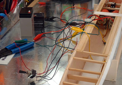
After I made my connections it was time to test and make sure everything worked. Do this as you complete a wiring section, it's much easier to check what you're working on one section at a time, rather than try to hunt down a problem later. Here you can see my mess of wires. I have used "test leads" I got from my local Radio Shack, these have alligator clips on each end to clamp onto your wires and quickly and easily check to make sure current is going through, and everything is working correctly. For this test I just connected the test leads to my wires on the switch and my motor, then from the middle batter poles on the switch to my battery. The motor came on, so my soldering had worked.
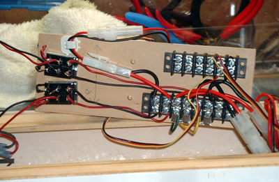
On the underside of the electronics board I decided to try using barrier strip terminals I also got from Radio Shack. My soldering is still mediocre at best, and I want to use this ship as a test bed for all my options for my next models. Strip terminals have two screws above each other, and can have 2, 4, or more sets of these screws. The idea is you connect one wire to the bottom screw, and then connect another wire to the top, thus completing a circuit with out splicing or soldering. I used the strips to connect my wires from the switch to the speed controller, and from the speed controller to each motor (reversing the polarity on one motor so it would run the opposite direction). You can see that I have a second switch as well; this was originally going to control any auxiliary functions such as lights and sound, along with having charging leads for the auxiliary battery. Unfortunately due to weight and the tight squeeze of my beam this is probably not going to be possible, but there are there if I should need them in the future. I really tried hard to keep my "clean" (wires from the reciever to speed control and servo) and "dirty" (wires from batteries to speed control, motors ect) on separate sides of the hull, and looking nice like so many pictures in the gallery. Usable space again prevented me from doing so, and I had to place items so they would fit, more than anything else.
Here you can see the board ready for test fitting in the hull, it was a tight squeeze! Notice the quick disconnects close to the forward battery. These come from wires on the battery and connect to plugs on the leads to the switch. There are similar connectors on the wires leading from the strip to the motors. This allows the entire electronics board to be unplugged and removed from the ship for maintenance or removing the main power supply.
Finally I hooked everything up and ran the system, to my utter surprise it worked! I must say I felt my skills had grown a lot during this phase, but I was still very happy everything worked the first time. I credit most of this to going slow and checking that each part worked before I started wiring another. I'll be the first to admit my wiring is not pretty, but I'm satisfied with it at this time, and feel I have skills that I can build on for my next model (with a wider beam!).
Inside the hull, everything cleared the deck, and still worked. I then put it in the pool for my first run under power. Worked great! One important note here, I have not permanently attached my propellers yet, they are hand screwed on right now. I did this because I have some nice brass ones I ordered from Loyalhanna Dockyard that I plan to install later. Also I don't want to put them on permanently until the hull is painted. I did not think this would be a problem, but just seconds after starting my engines I watched as one of the props spun off and sank to the bottom of the pool. Lucky for me this was not a big deal, I just jumped in and fished it out, but if your going to test in the murky waters of a local pond, it's something to think about. A bathtub would allow you to make sure everything works, and still recover your props should one spin off.
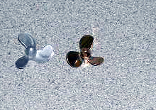
Here is a photo of the props, the silver is what came with the kit, and the brass are the ones I ordered. These props look fantastic! I can't seem to get a close photo that's not blurry of them to show though. I am very satisfied with my purchase, and Don at Loyalhanna helped me figure out what size I needed, even going as far as contacting the manufacturer of my Kit in England to get the correct thread size. Great customer service, I highly recommend contacting him if you have any questions, he is extremely knowledgeable, and very helpful to the beginner!
Well that's it for my overview of the mechanicals on my ship. The only thing left was to get final inspection before sending her down the line for superstructure construction. Here you can see inspectors 1 and 2 giving the hull a final look over before putting their paw of approval on this phase. I'm not sure what they find so interesting near the battery; perhaps they are making bets as to when the wiring will cause a "cat" astropifc fire. Who knows?
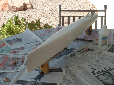
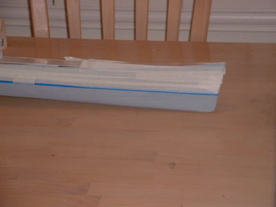
After hearing from several members from the forum I decided now would be the time to paint my hull, before I started sticking delicate pieces to it. The fist thing I did was clean the hull, first with mild soap and water, then with a light coat of rubbing alcohol just to make sure it was really clean. The reason for this step, as I was told, is to insure that all release agents used in getting the hull out of it's mold are cleaned off before painting. These release agents could cause the paint to bubble, or not dry completely. Once the hull was cleaned I taped off the ends of the prop shafts to protect the threads. I used automotive spray can primer for the hull, in a light gray. In retrospect I should have used white. The gray primer caused my paint to "darken" more than I would have liked.
Here you can see the hull just after cleaning.
After the primer had dried, VERY quickly here in Arizona, it was time to put the paint on. First I used a water line tool I bought from MicroMark to re-draw my water line. Then I drew another line above it to mark the top of the "boot toping". The boot topping is the painted area above the waterline; on my ship it's black. On real ships the boot toping is used to show how low or high the ship is sitting in the water as well as to hide any "scum" line that might form at water level. I used a low tack sign tape to mark off the waterline. The easiest way I found to put the tape on evenly was not to cut it into little strips. Instead I found that just putting on as one long piece all the way around the hull made it easier for me to place it right on my drawn waterline. I had planned to use the tape along with a roll of masking paper to cover the areas I was not ready to paint yet. This in practice did not work well for me! The roll was hard to handle in one hand with tape in the other. On more than one occasion it fell out of my hand, rolled across the floor and was promptly attacked by the awaiting cats. Finally I decided just to do exactly what my directions said not too, and use masking tape. The tape did leave a little bit of gum on the hull after removal, but I was able to wipe it off with my fingers in a rolling motion.
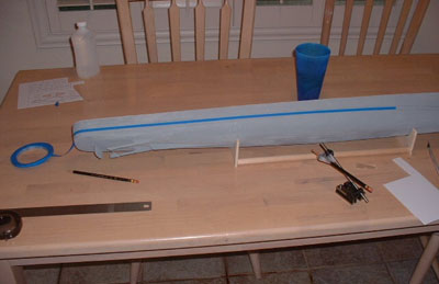
Here you see me applying the tape along the water line. Note the waterline tool with pencil attached, you can also make one of these, directions are on the how to pages.
Here it is taped off after I gave up on using masking paper.
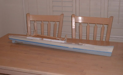
More tape, hey what else are you going to do with all that masking tape you have been saving for so many years?
For the antifouling red on the bottom I used Model Master Insignia Red. I wanted a deeper red, as the hulls I have seen pictures of were not a fire red color. This worked really well, but I'm not sure if it was the paint it's self so much as the gray primer underneath.
For the actual paint I used an airbrush I got used at a garage sale. It was in decent shape, and all I did was replace the "needle" (the spray tip). I got a double action one, which is nice because I can control the amount of paint being used instead of just having a pre-set stream. Airbrushes range in price new from $30 to $200 or more, but check local pawnshops, as I have seen them there used. I started using the little cans of compressed air they sell at the hobby store as propellant, but soon realized that they did not work that great, and at a cost of about 6 bucks a can, it would get REALLY expensive in the long run. I switched to a compressor and it was a night and day difference, the paint looked good, and the airflow gave me better control. Highly recommend it if you can afford it, or find a good one used, or borrow one like I did.
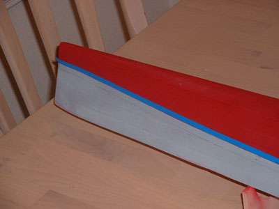
Here you can see the hull red, and the results of using an airbrush and compressor.
I then painted the boot topping black, using the same masking procedures. After that I painted the hull to match the Measure 21 used on the USS Stevens. I had pictures of this, but lost them in my big computer crash this past weekend. No doubt the work of gremlins, because I NEVER make computer mistakes! J I will take some more and add them to my next update. I used the paints offered by Snyder and Short, and am very happy with them. They come in small cans though, about have the size of a regular model paint jar, so be sure to buy enough. The upper hull and deck did not quite come out as I envisioned though, not the paints fault, but the gray primer I used. This darkened up the hull paint, and made the two shades of blue, one for the hull, one for the deck look the wrong shade. Live and learn I guess, use a white primer if you need to paint the hull other than gray!
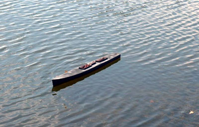
This is my ship on a test run at the local pond; here you can see how dark the paint came out.
The next step was to start on the superstructure. As I stated above, it was my intent to create the USS Stevens, and have a Kingfisher plane on deck. With my model already so heavy, I have decided that at this point I'll just stick with the kit and build the Fletcher. My artistic aspirations have been overcome by the desire to actually run this boat in the water and not have it capsize. That being the case, I am building my superstructure as included with the kit, instead of scratch building the round bridge Stevens. As my skills increase perhaps I can come back and try that ship again.
Ok, the first step was to get all my sheets of styrene out and organized. As I said before, each panel needed for the construction is marked with a number. One thing I found out too late was that not all these numbers are actually on the pieces, some are above or next too, so keep a pen handy and write the number on the pieces after you cut it out.
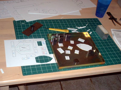
Here you can see me in the process of cutting out the pieces and putting them together to form the pilothouse.
Cutting this stuff was kind of an enigma to me at first. I could not seem to cut a straight line to save my life. After some experimentation I realized that you did not actually need to cut this stuff very deep, a surprisingly light score is all that is really needed. Once you score the lines, simply bend the piece down and it comes right out. You can use a hobby knife, or I really like the little "plastic cutter" MicroMark sells for a few dollars (seen with the yellow handle in the photos). Then just use a straight edge as you guide and it comes out really good, I was putting to much effort into it, thus making it harder than it needed to be. Don't over cut the stuff, just score and pop out. After you have the piece cut run all the edges lightly across a piece of fine sandpaper secure to a scrap block of wood. This helps you get a smoother edge for gluing.
For glue I used what is called Plastic Weld, and it is made specifically to bond these types on plastic to each other. It works on some molecular level I guess, but in reality what it appears to me to do is just melt the two pieces together. I guess that calling it "Plastic Melter Stuff" would not be as good for marketing. Anyway is pretty easy to use. You line up the pieces to be glued so that they form an edge, and then just use the brush on the end of the cap to quickly wipe some glue along the seam. The capillary action sucks the stuff into the seam and "welds" it together. This stuff evaporates very quickly, so work fast when wiping it on the seam. It can be hard to hold the applicator, and both the pieces tight together so you can use various things to help you. I purchased the metal jig shown in the photos, again from MicroMark, but in retrospect you could just make one. All the thing is, is a piece of metal with magnets. These can all be bought at the hardware store, and make your own. Anyone want to buy mine for the 20 bucks I spent? J Anyway, using this just put your two pieces together using a magnet on each side to hold in place, they apply the glue. After it sits for a few minuets I add a line of glue to the other side of the seam. Leave this stuff at least 12 hours to let it completely weld the joints, after that it's a pretty strong bond.
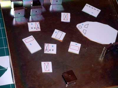
Here is a close up of the pieces cut, sanded and ready to be glued together.
Well that's it for this update, my progress has slowed due to school, but I'm still working on it!
![]()

Back to Warship Models Underway
 This page maintained by Kurt Greiner.
Email me here.
This page maintained by Kurt Greiner.
Email me here.
This page viewed 69
Version 1.3
Last update 09/02