


Click on any image that has a border to enlarge. -
Kurt's note: This page will be devoted to the step by step construction of this large model of the US Navy's latest Amphibious Landing Ship. Many thanks for Jeff for taking the time to thoroughly document his project!
Click on any picture for a larger version
Hello, I hope you enjoy viewing my progress of building the LPD-17 USS San Antonio. The model is 86 inches long (7ft. 3in.) and is 1/96 scale. When this model is complete, I plan to have working bay doors and a radio control LCAC hovercraft come out the stern.. A GREAT DEAL of research has been made by me on this ship. It hasn't even been built yet by Avondale Shipyard. As I find out more information, things will probably change in building this model. IF YOU HAVE ANY INFO on this ship or even builders plans in scale, PLEASE email me. They are greatly needed.
JUNE 14 - JULY 7
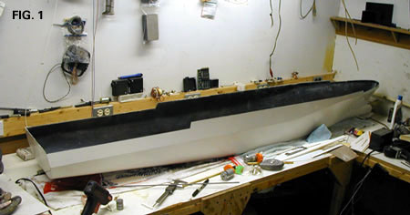
FIGURE 1 displays the hull as it came from the manufacturer Scale Shipyard. This model is quite large and takes a good amount of space to build. Not recommended for those who live in an apartment. :-) The hull is very nice and smooth on the outside and has been built to show locations of the helicopter bay and the for superstructure. The well deck walls are added all the way up to the flight deck. The only problems I found with the hull are:
1. No anchor bolsters were molded in, and
2. No marks for the shafts and struts.
Usually they are displayed but as you can see, I have already added the running gear. I will add the anchor bolsters later. The plans for this ship are also out of date. New plans will eventually be made but until then, I am on my own.
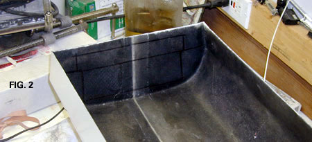
FIGURE 2 displays the line in which I will cut into the hull for the bay doors. The bay doors will open and close by radio control.
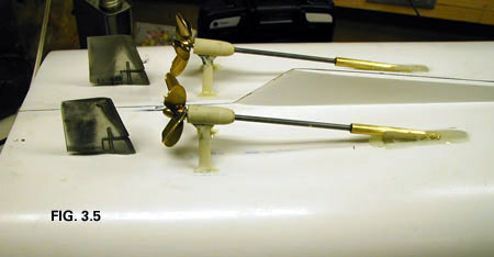
As you can see in FIGURE 3 - 3.5 I have added the running gear (Shafts, Props, Struts, and Rudders). The one thing that I don't like about Scale Shipyard is that they never send Rudders with the hulls. (Editors note; this depends on the hull; some do include rudders, and some have them available as an option; check the Scale Shipyard catalog for more details.) I suppose that I could ask but as you can see, I made my own using plexiglass. I have cut them using the plans. They have been filleted and work very well. The epoxy used to install the running gear has also been sanded down.
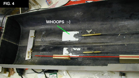
FIGURE 4 shows my mistake in installing the running gear. If I HAD the marks for the running gear this may not have happened. I had cut the whole into the hull too long and the stuffing tube was very loose in the hull. I re-glued 2 sheets of styrene over the holes and used JB-Weld for glue the inside of the hull... LET'S SEE WATER GET IN THERE NOW! :-) The outside is all epoxied and sanded nice and everything is ok. You can also see the rudder mechanism for steering. The red tube will be attached to a servo in the center of the hull near the motors.
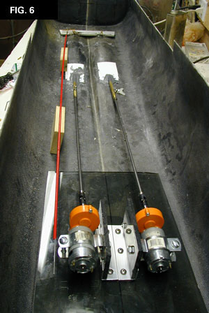
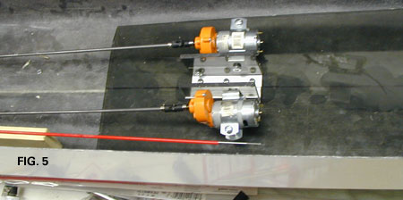
FIGURES 5, 6 A cable is inside the tube to allow the servo to push the rudder. The motors for this model are geared 3:1 and will be direct driven using a 6V battery pack.
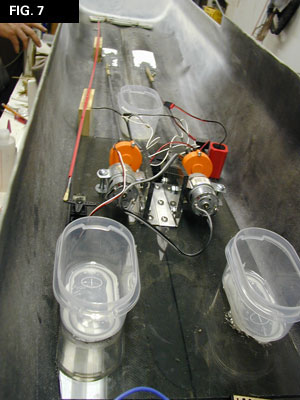
FIGURE 7 displays the containers that I will use for ballast. You can also see that I have added the electronics for the radio. Tupperware containers are great because you can add the ballast and it will never shift around inside the hull. If all goes well, I won't ever have to get into the stern to play with ballast. Since the well deck is covering most of the ballast, I can't get back there anyway. Lead will be melted and placed into the containers for ballast. It takes a LOT of weight to get this hull on the waterline. The bow structure will have to be separate from the hull in order to get into the bow and add ballast.
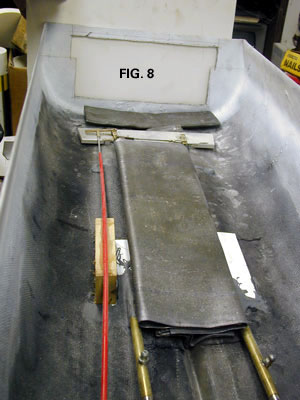
FIGURE 8 displays the hole that was cut for the well deck and the ballast that will be underneath. The walls have been painted white inside the bay and I am currently building the deck and working on the operational doors. More photos will come soon displaying a painted hull and working bay door with planked well deck.
AUGUST 2002
Please bear with me as I continue my process of building the USS San Antonio. This ship is 7 feet 3 inches long and I have to store it at my parents house. I can only get to it on the weekends so my time is cut in half and it will take longer to show the progress. NOTE: 80% of my research is coming from the LPD-17 website www.lpd17.com and there are plenty of movies showing a 3D model. My ship will be designed and built to match the one on the movie. That's the closest I can come for now until the real one is built. I have also been in touch with some of the builders and getting info.
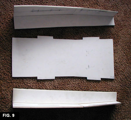
Fig. 9 displays the gator board used to create the well deck. The well of the LPD-17 is bowed outward toward the stern of the ship. I have used the plans that came with the hull to create this part. The plans seem accurate to the ship but this ship is still being built. These parts are glued together to form the well.
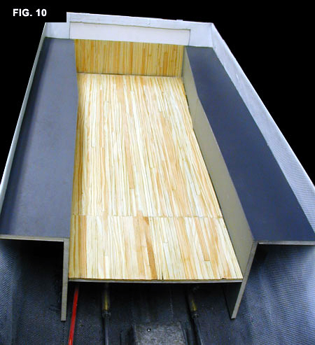
In Fig. 10 you can see that I have planked the well deck and installed it. The well deck was planked using pine strips from doll house flooring. It is in scale. I am not completely sure if this deck is actually going to be planked or not. Some 3D photos show planked and some don't. I like it planked and it will stay that way for a while. You can see that the well is bowed outward toward the stern to allow a LCAC hovercraft to enter.
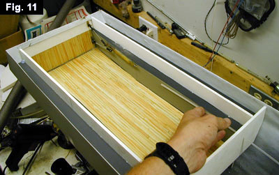
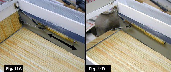
I have now added the walls of the well deck. After a lot of thought from "The engineering guru" Franklin York (my father) a mechanism to open the doors has been made. He takes full credit for creating the movement. I knew how I wanted it to work and he made it happen. Figure 11 will show the the process were a tube for the shaft will be placed. Figure 11A/B shows it in better detail. A motor will push and pull the joints attached to the bay door to open and close it. The brass square tubing acts like a slide and bell cranks are attached.
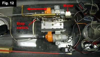
The motor is shown in Figure 12. When the motor spins it will turn a threaded shaft and push the rod in and out. A stop switch has been placed to prevent it from going to far. This whole part has been clamped in so that if I have a problem with it, I can always pull it out from the aft mast when the ship is completed. So far, it doesn't look like there will be a problem. It works great and will run from my transmitter battery pack.
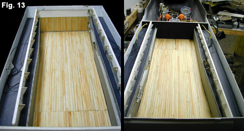
Fig. 13... I have cut out small triangles from .20mm balsa wood and added the girders on the ceiling. Again, all this info is coming from photos on the LPD-17 website. I have also lighted the well deck and you can see the wires on the sides of the hull. These lights are along side of the well and will light it up since it gets dark in there. Even though the US Marine Corp is not afraid of the dark, I thought people would like to see inside the ship. You can barely see them in the photo but there are 3 marines along the starboard side if the ship. Soon you will see the result of my work so far.

Figure 13B is where the lighting has been placed.
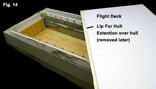
In Fig. 14 I will now add the flight deck and the entire well deck will be enclosed. A lip is always cut in gator board to allow a proper fit. Gator board is foam core with 2 sheets of plastic on the surface. I cut through everything but 1 sheet of plastic which will go over the hull. This lip will be removed when the glue dries and a nice fitting deck is secured. Nice and smooth to the hull.
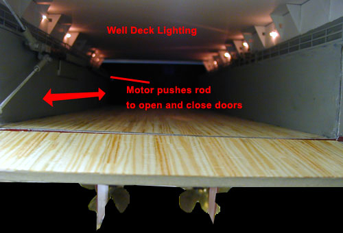
Figure 15 shows my well deck all lit up and pretty. This is the view if you were on the LCAC coming back from a patrol.

Figure 16 just shows what I mean when I use an extra lip. It will extend out from the hull a bit. This way, you don't get stuck with a deck that doesn't fit. This fits every time! Just cut off the excess and your done.
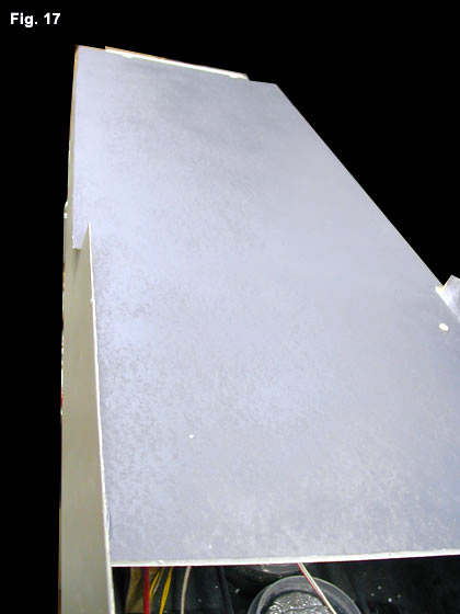
Figure 17. The flight deck is now on. I cant wait to add those helicopter and marines all over it. :-)
JANUARY 21, 2003
Hello again,
Well in the last 4 months I have been doing more research on the LPD-17 and I was able to take some photos of the LPD-21 model stationed on the USS Intrepid museum in NYC. This model answered a lot of questions for me but it was a (stand away) model and not very detailed. I am using video footage from the lpd17.com website to build my model as well as some comments from Avondale shipyard. The ship will obviously go through some more changes while it is being built but I am confident that my model will come out looking exactly like it will be built in life. Below are some more photos displaying my progress with the superstructure. Since it has been a while, I have lost a few photos showing progress on the bay housing as built. Other photos will show how models are put together though.
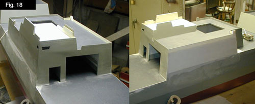
Fig. 18 In Fig. 18 you can see that I have built the helicopter bay and aft superstructure. This will have 1 large hanger bay and 1 smaller door for vehicles etc. You can also see the location of the flight control center.
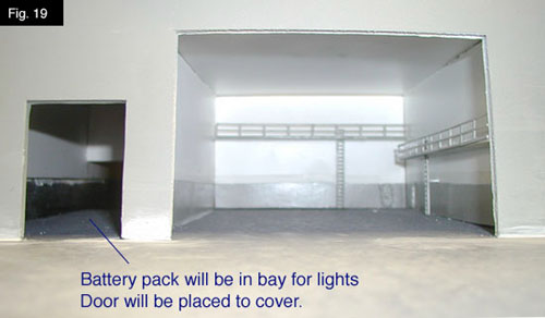
Fig. 19 This is a view of the hanger bay. An MV22 Osprey will most likely be fixed inside this hanger but I have added the shelves, ladders, and doors. I plan to add my battery pack in the housing on the left for the lights. The next few photos will show more steps on building the rest of the structure.
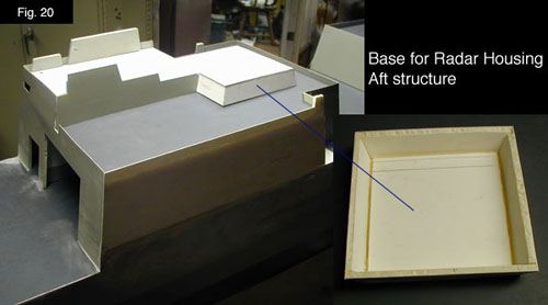
Fig. 20 You can see here the bottom housing for the radar. This is four pieces of gatorboard glued together with a fifth top piece as a roof. All the sides of this ship are angled for anti-radar capability. Although, mine will most likely show up. :-)

Fig. 20a. I have been building more areas of the superstructure. A strip of styrene is used to add thickness for the sides that act like rails. This also adds strength to the model. The hole in the top was kept so that I can get inside to the motors, etc. in case there is a problem later. Doors have also been added to the ship in location. A fitting set for this ship can be purchased from the Scale Shipyard. The entire ship will have a new paintjob on my next posting of this model.
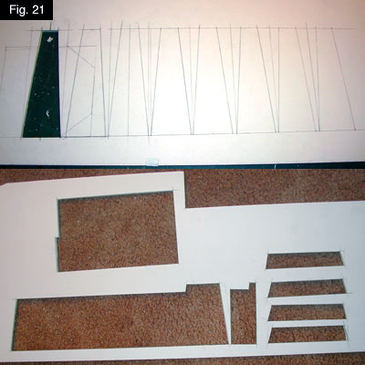
Fig. 21 This figure displays my cut lines for some of the pieces of this model. For those starting out, this can give you a better idea of how models are created. I simply trace the plans for both sides and transfer them to gator board. I then cut them out and glue them together. With the top and side view, this should come out correct. you can do this for all parts of the structure.
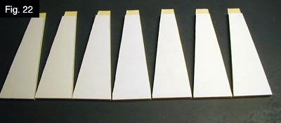
Fig. 22 The radar is housed on this ship to make it anti-radar capable. These are triangle shaped at the same size. With all of them glued together, you get an octagon shape like a cone.
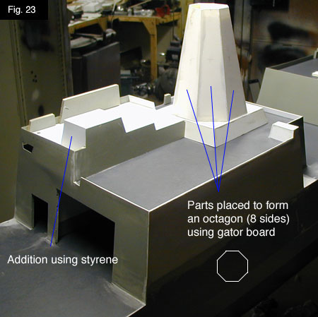
Fig. 23 The radar is now glued together and in place. I actually made the radar too low and re-created it the way it should be. Other parts of the structure can be seen to make shape.
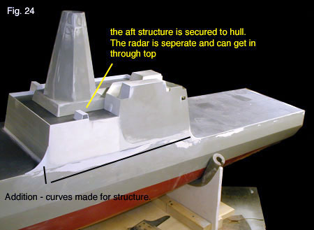
Fig. 24 The aft superstructure is coming out nice. I have added the curved sections of the structure. This is now all re puttied to a smooth finish and ready for a paint job. The aft section is secured to the hull. With the hole under the radar I can easily get inside. I will complete the flight control section and get ready to paint next.
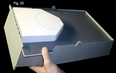
Fig. 25 This is the forward superstructure. Again, I apologize for losing some photos but I think that you can see from previous photos how the structure was cut and glued. I have cut the windows for the bridge and started adding the next deck level.
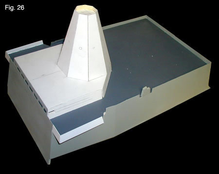
Fig. 26 The sides of the deck are being added and the radar is glued and secured to the bridge. Styrene strips were used for the sides of the hull (white).

Fig. 27 Another view of the forward structure. Now the aft section of the bridge is complete. The bay for the raft is also shown. All the sides have been added for support. Everything is puttied and smooth and ready for paint.
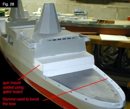
Fig. 28 The forward deck has been added. I still have to create the part for the gun mount. You can see that this part of the structure will come off the ship. I will be able to add ballast to the bow after transporting it. Keep it down in weight for carrying as well. This thing is heavy. I haven't weighed it yet but I'd say about 80lbs so far. The bow is also complete. The bow of the ship has a beveled edge.
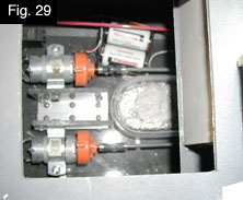
Fig. 29 This is a view through the stern radar section. You can see that I can get to my motors and other parts if I need to. The hole is about 5" x 5".
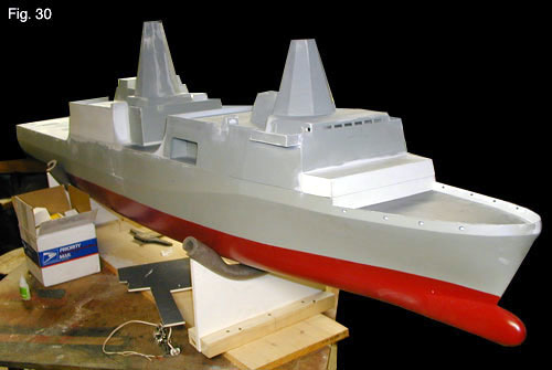
Fig. 30 Well, here she is. The USS San Antonio. Looking pretty good so far. It is now ready for its second paint job. Next posting will show the paintjob and fittings placed. If you need them, I suggest the vendors on this site. There are very few fittings on the new types of warships. This part shouldn't take too long.
Keep in touch and stay posted for my next round.
![]()

Back to Warship Models Underway
 This page maintained by Kurt Greiner.
Email me here.
This page maintained by Kurt Greiner.
Email me here.
This page viewed 171
Version 1.2
Last update 01/03