
 You will need a # 1 Screwdriver
iFixit Jimmy, or similar thin tool (like a guitar pick) to pry
#51, 1/8". 3/16" and 7/32" drill bits
A drill bit holder
A soldering iron (I love my Hakko
FX88DX, but any small soldering
iron will do)
A razor saw or some other way to cut metal bar and tubing. A
cheap aluminum miter box is
helpful
A 3d Printer or access to one. I used a Bambu
Mini-A1 which has been rock solid for me. (Not an affiliate link, I just recommend
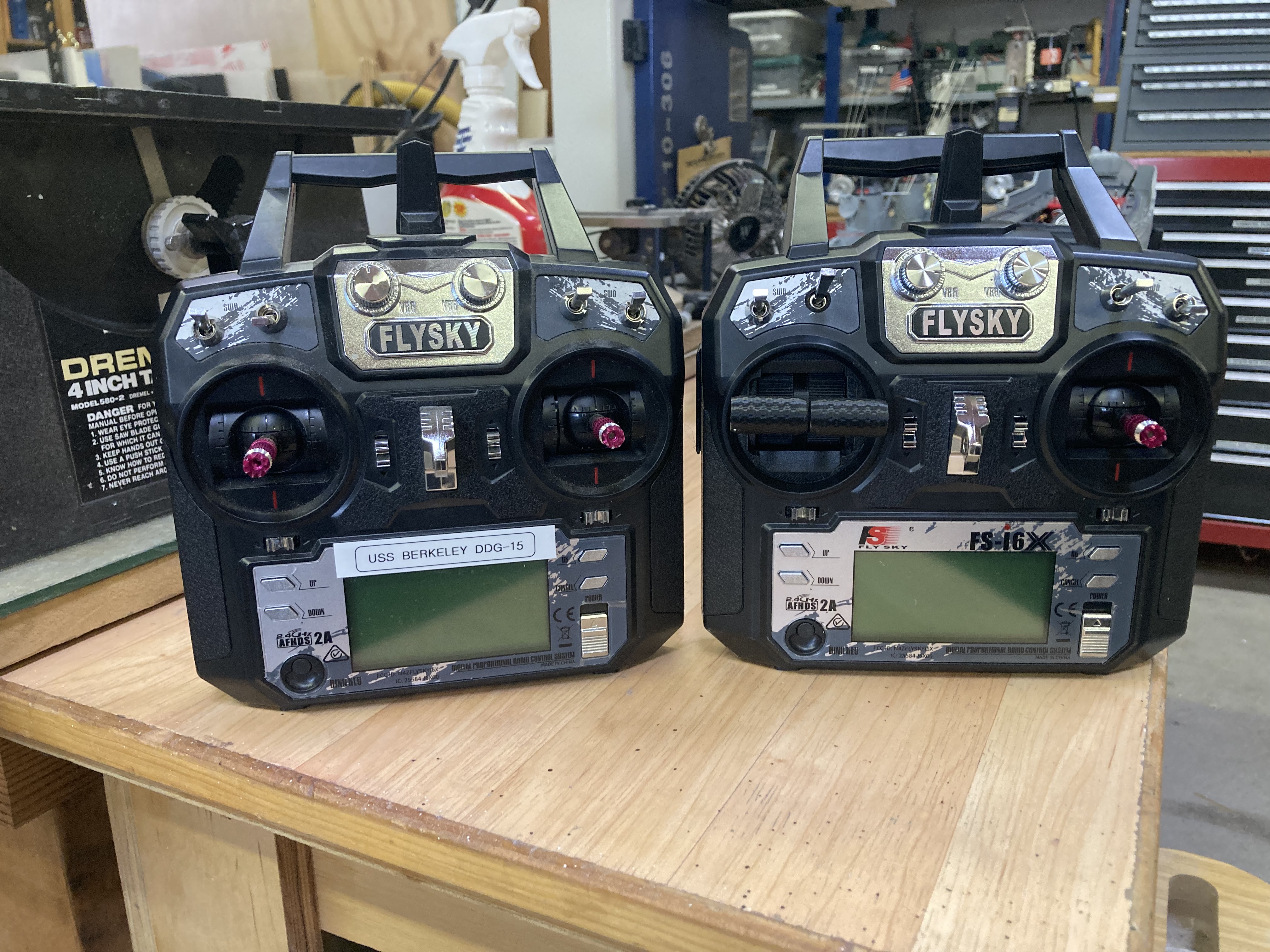
this printer) You will need a Flysky Fs-i6X radio or
equivalent. This conversion my fit other Flysky radio in
that series, but has not been tested.
K&S brass tubing 7/32"
3/16 diameter solid brass or
stainless steel round bar
3/16 diameter solid aluminum round bar
Thin solder (I like .032 diameter 63/37 flux core solder if you can
find it)
Soldering flux - highly
recommended for better flow, even if you are using flux core solder
Thin heat shrink tubing
9 inches of 24 gauge or similar stranded (flexible) wire
Small Screws; 6 1.7mm x 8mm self tapping screws, and 4 2.3mm x 10mm self tapping screws (this is the assortment
I purchased for this project that has them)
Small amount of Vaseline
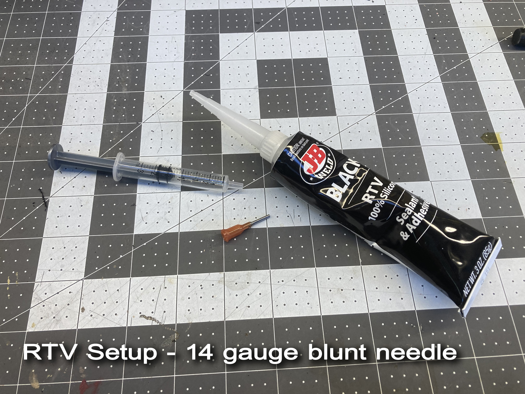
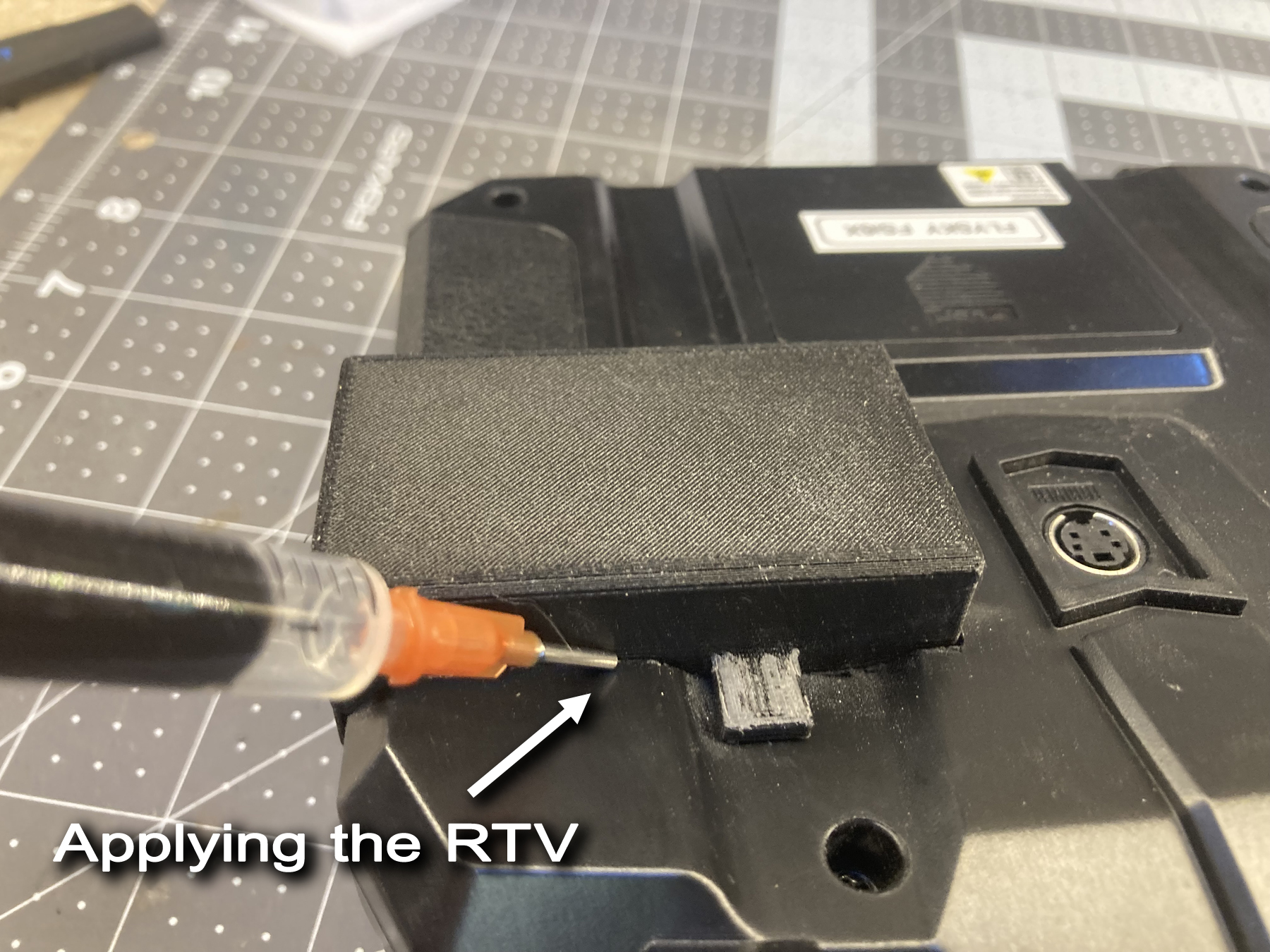
Black RTV sealant
Filament for the printer. I
recommend PETG,
which is what I used. The color is up to you, but I found
that black looks nice with this radio, a contrasting center
support will look sharp, perhaps in red.
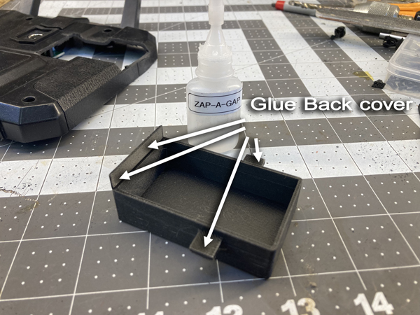
Medium viscosity CA glue. I use Zap-A- Gap.
Thin CA glue.
Sanding stick or metal file to chamfer the edges of the metal parts as
indicated
A Fine point Sharpie felt pen
A pencil
You will need a # 1 Screwdriver
iFixit Jimmy, or similar thin tool (like a guitar pick) to pry
#51, 1/8". 3/16" and 7/32" drill bits
A drill bit holder
A soldering iron (I love my Hakko
FX88DX, but any small soldering
iron will do)
A razor saw or some other way to cut metal bar and tubing. A
cheap aluminum miter box is
helpful
A 3d Printer or access to one. I used a Bambu
Mini-A1 which has been rock solid for me. (Not an affiliate link, I just recommend
this printer) You will need a Flysky Fs-i6X radio or
equivalent. This conversion my fit other Flysky radio in
that series, but has not been tested.
K&S brass tubing 7/32"
3/16 diameter solid brass or
stainless steel round bar
3/16 diameter solid aluminum round bar
Thin solder (I like .032 diameter 63/37 flux core solder if you can
find it)
Soldering flux - highly
recommended for better flow, even if you are using flux core solder
Thin heat shrink tubing
9 inches of 24 gauge or similar stranded (flexible) wire
Small Screws; 6 1.7mm x 8mm self tapping screws, and 4 2.3mm x 10mm self tapping screws (this is the assortment
I purchased for this project that has them)
Small amount of Vaseline
Black RTV sealant
Filament for the printer. I
recommend PETG,
which is what I used. The color is up to you, but I found
that black looks nice with this radio, a contrasting center
support will look sharp, perhaps in red.
Medium viscosity CA glue. I use Zap-A- Gap.
Thin CA glue.
Sanding stick or metal file to chamfer the edges of the metal parts as
indicated
A Fine point Sharpie felt pen
A pencil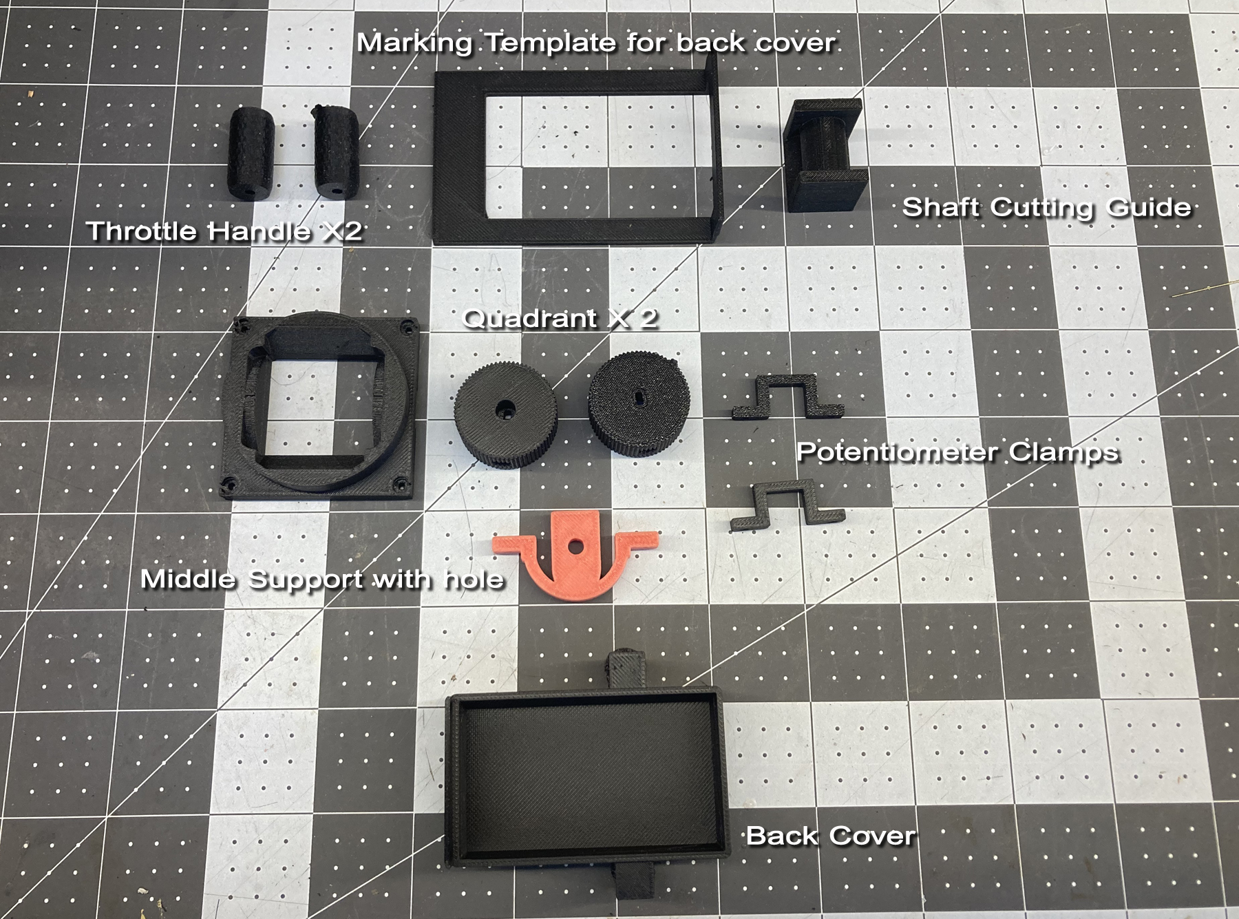
 Quadrants
Throttle handle
Bezel
Marking Template
Shaft cutting Guide
Middle Support with Hole Drill guide
Back Cover
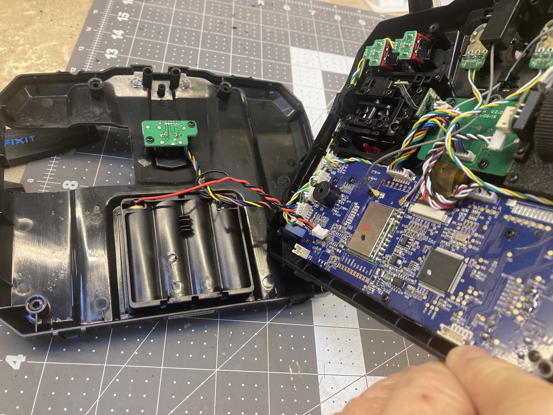
Remove the batteries to the transmitter
Take the back of the radio off by removing 4 screws and gently prying
the radio halves away from each other. A guitar pick or other
thin flat tool is useful for this, as is a dedicated pry tool, like the
iFixit Jimmy
Quadrants
Throttle handle
Bezel
Marking Template
Shaft cutting Guide
Middle Support with Hole Drill guide
Back Cover
Remove the batteries to the transmitter
Take the back of the radio off by removing 4 screws and gently prying
the radio halves away from each other. A guitar pick or other
thin flat tool is useful for this, as is a dedicated pry tool, like the
iFixit Jimmy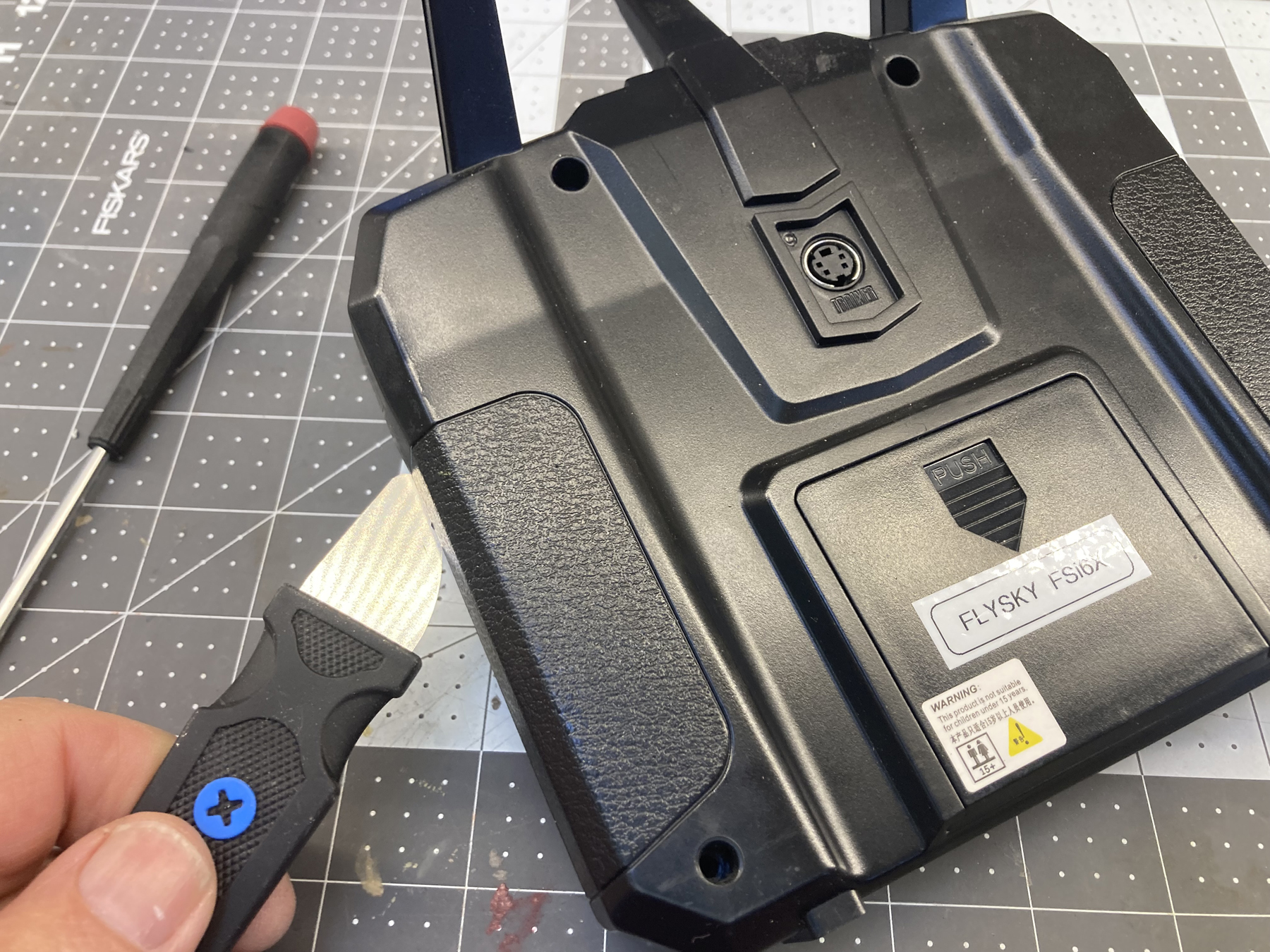 .
.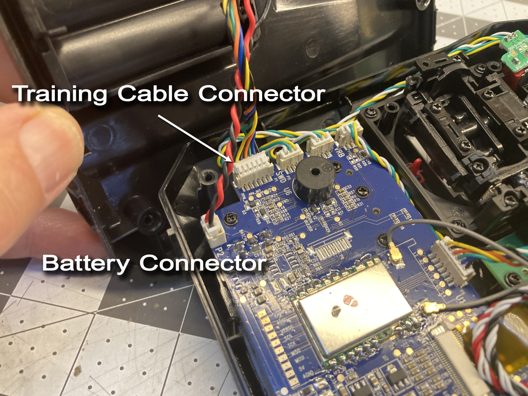 Unplug the four pin connector from left side of the existing gimbal
assembly
Unplug the four pin connector from left side of the existing gimbal
assembly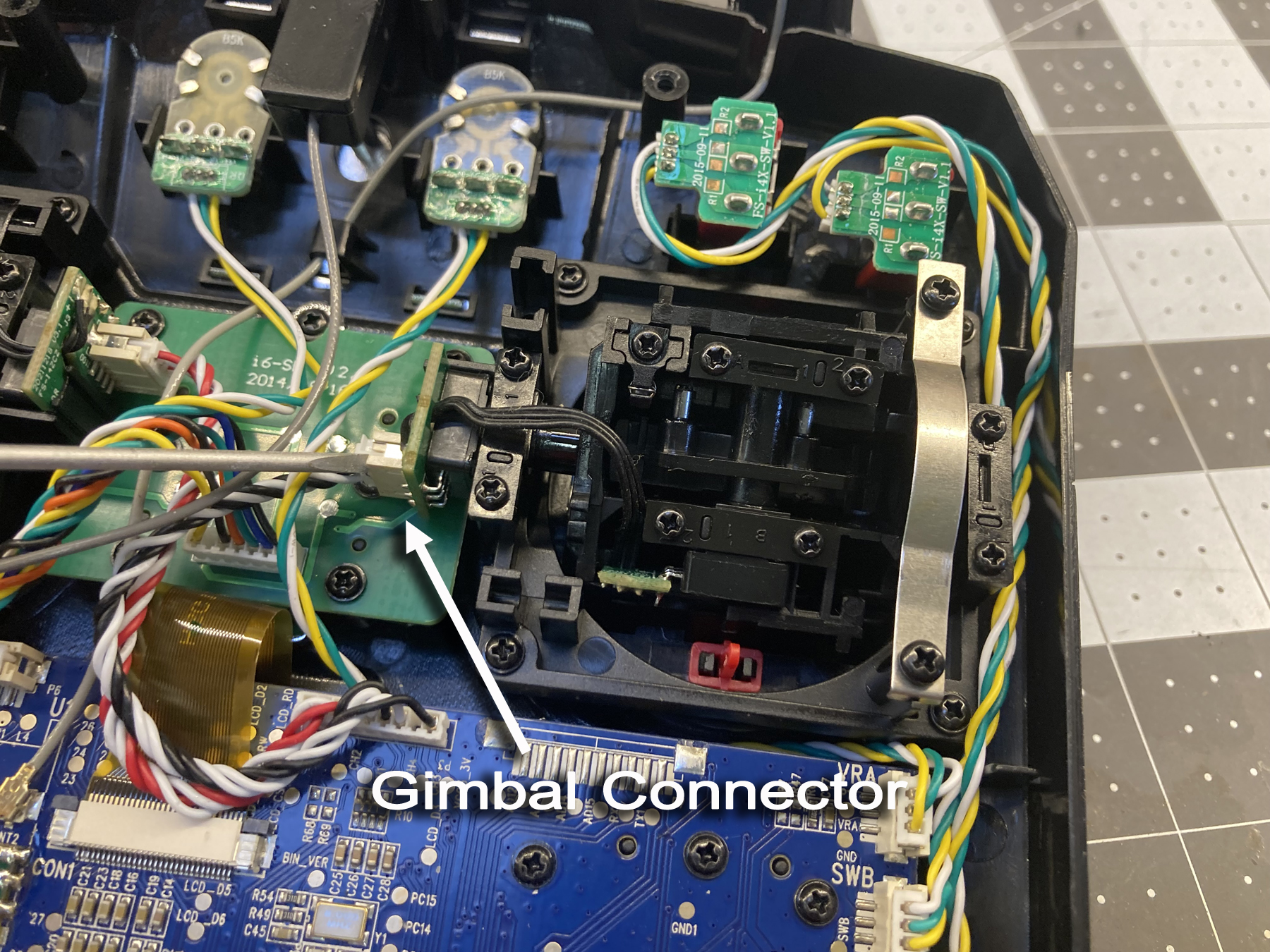 Remove the four screws holding the gimbal assembly to the transmitter.
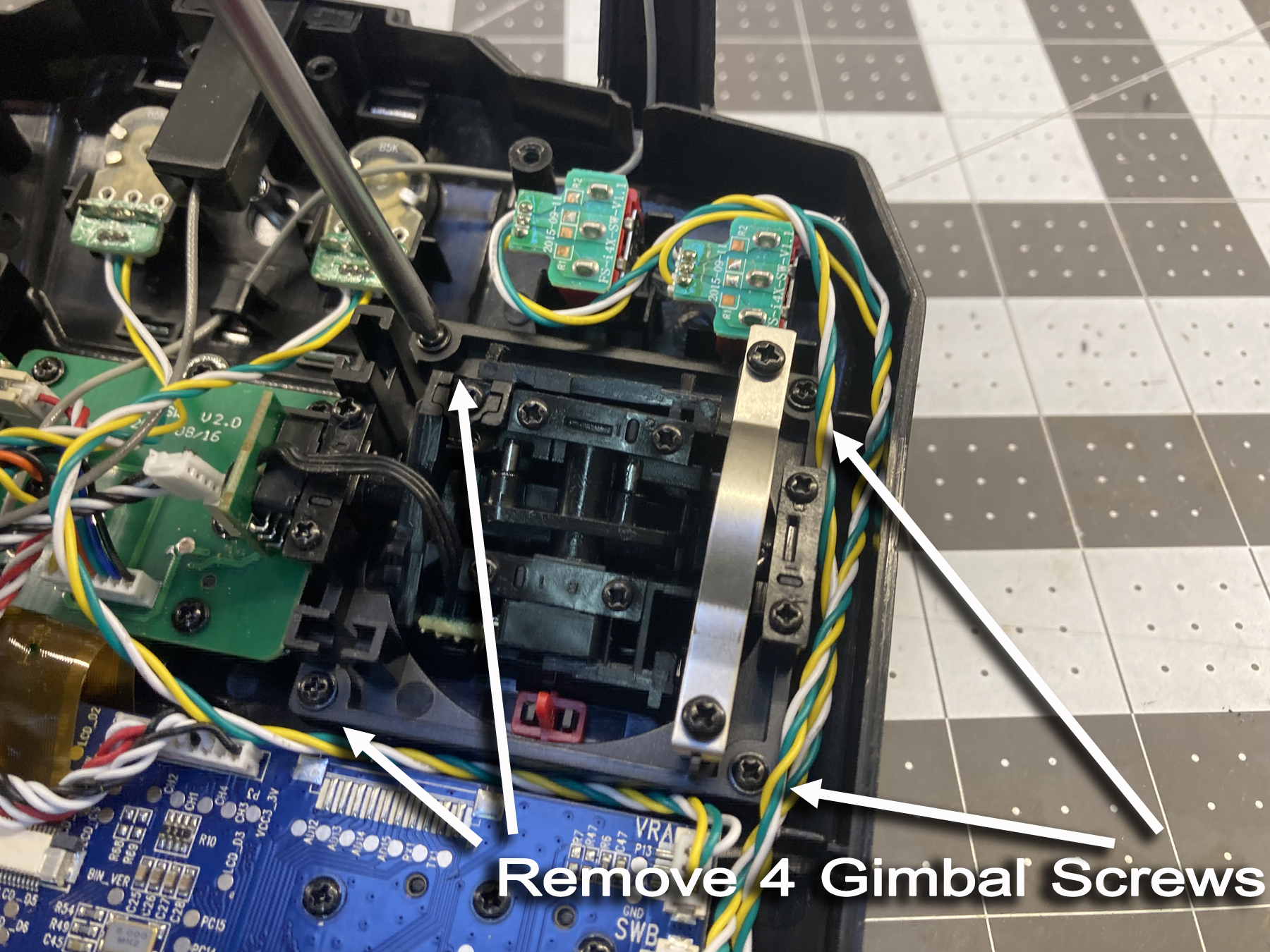 Remove the gimbal from the transmitter.
 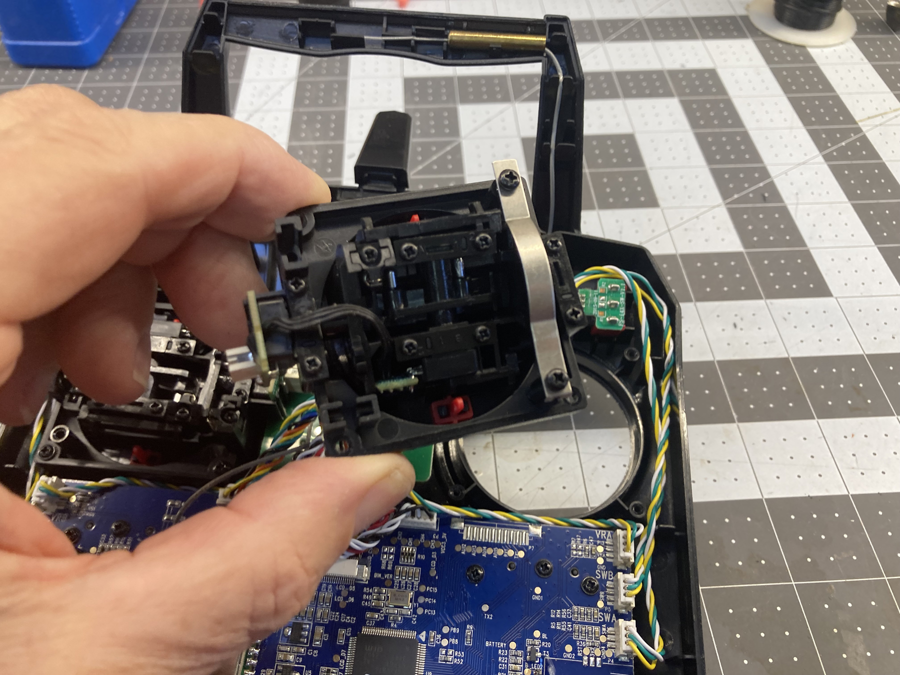 Place transmitter and rear cover away from the workbench to protect it
from metal filings and powder from future steps.
Place transmitter and rear cover away from the workbench to protect it
from metal filings and powder from future steps.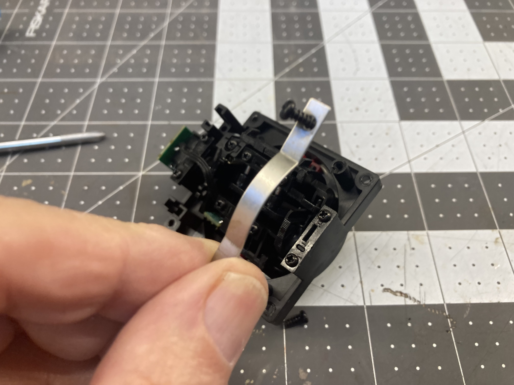
 At this point I have found it helpful to reinforce the wires where they
exit the pots with a drop of hot melt glue on each pot circuit board,
encapsulating those wires. Let it cool
At this point I have found it helpful to reinforce the wires where they
exit the pots with a drop of hot melt glue on each pot circuit board,
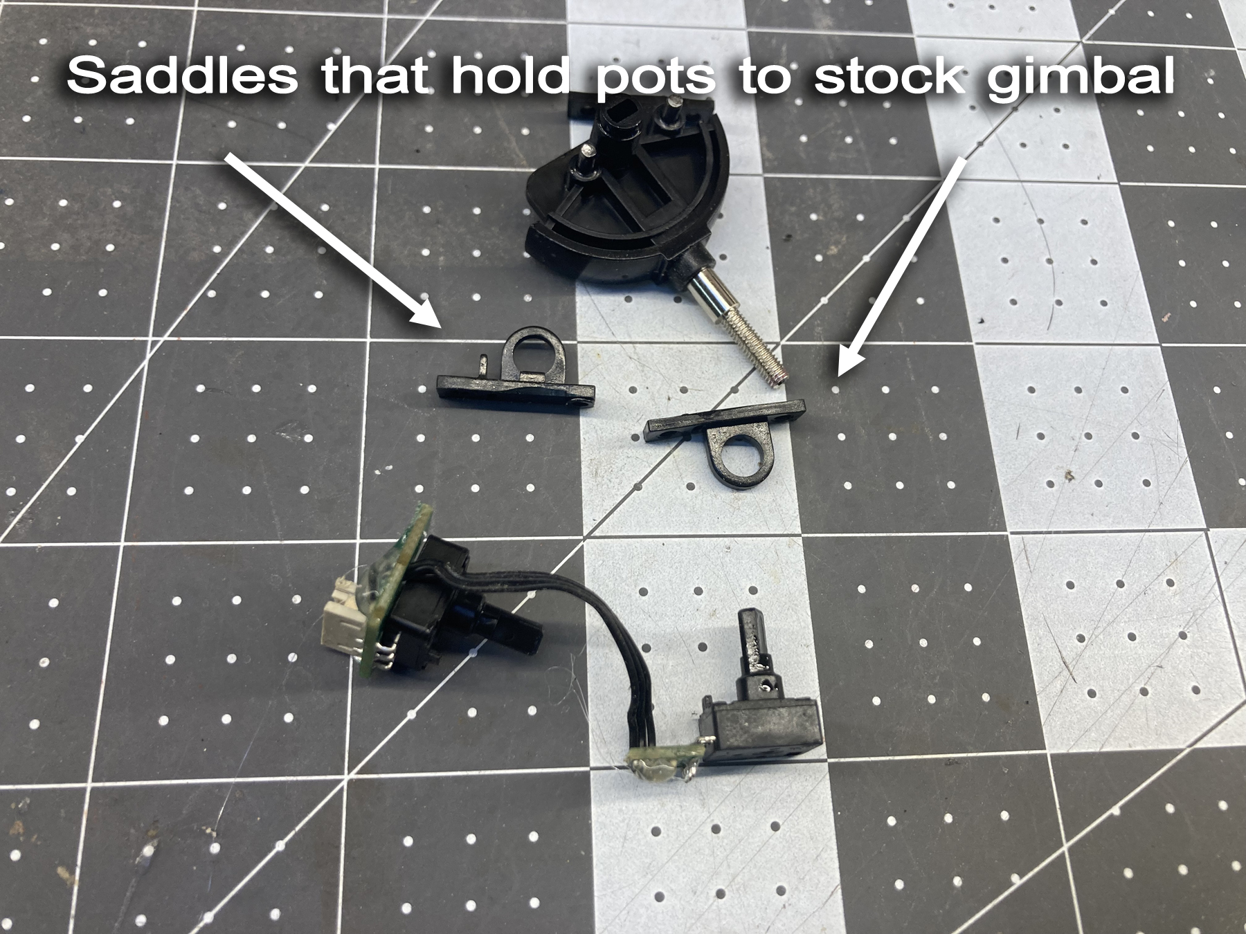
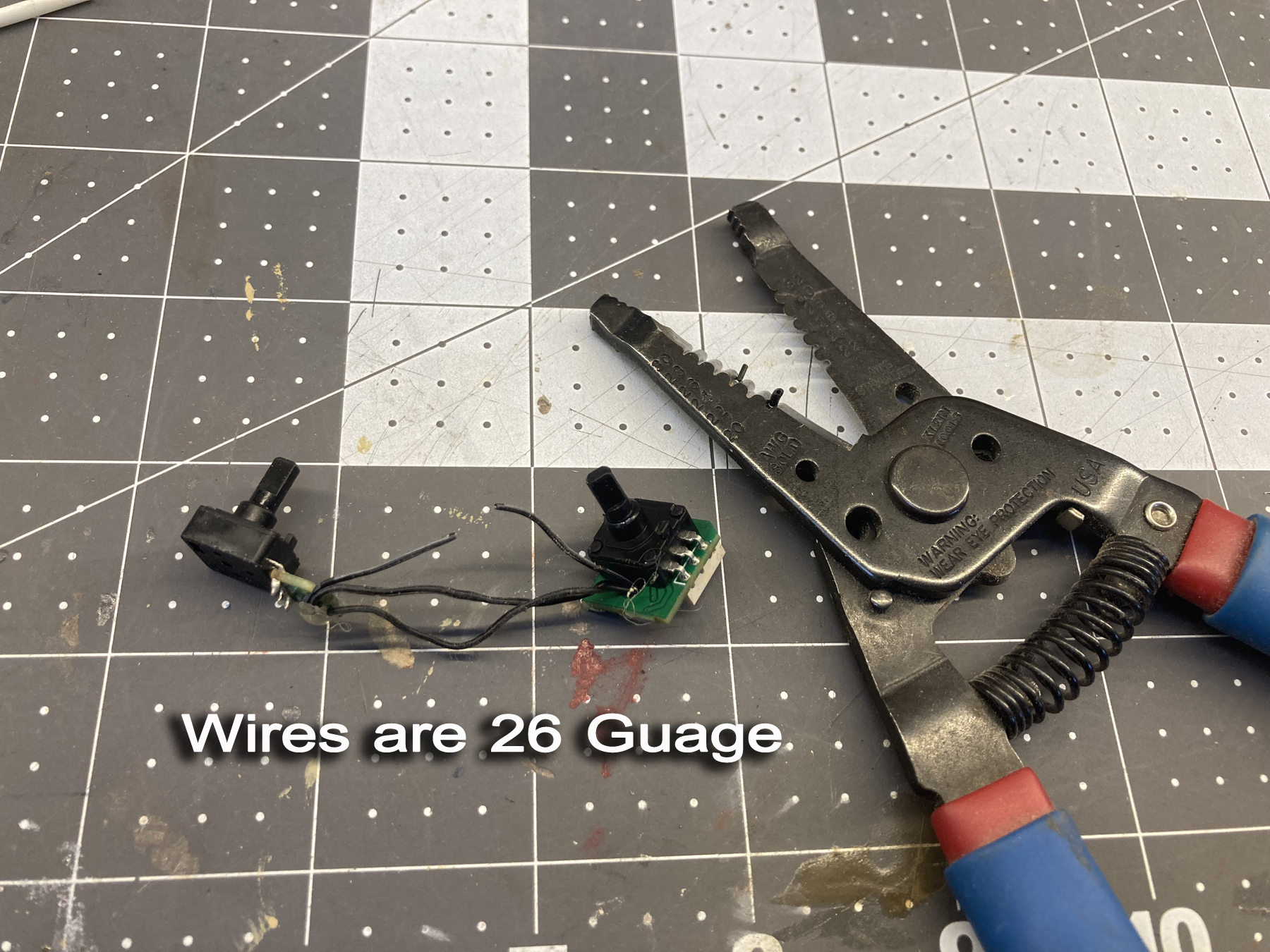
encapsulating those wires. Let it cool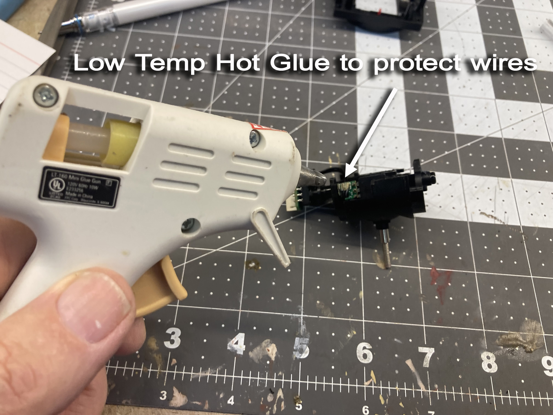 Remove the two potentiometers. Be careful to not stress the
solder connections to the small circuit boards.
There are three 26 guage wires that connect the two potentiometers
together. Cut them, one at a time, and insert a 3 1/2"
extension between each. Make sure you have a good connection and
cover them with heat shrink tubing. Don't forget to slide
the heat shrink on before you solder! Use a heat gun and
shrink both ends before proceeding.
Remove the two potentiometers. Be careful to not stress the
solder connections to the small circuit boards.
There are three 26 guage wires that connect the two potentiometers
together. Cut them, one at a time, and insert a 3 1/2"
extension between each. Make sure you have a good connection and
cover them with heat shrink tubing. Don't forget to slide
the heat shrink on before you solder! Use a heat gun and
shrink both ends before proceeding.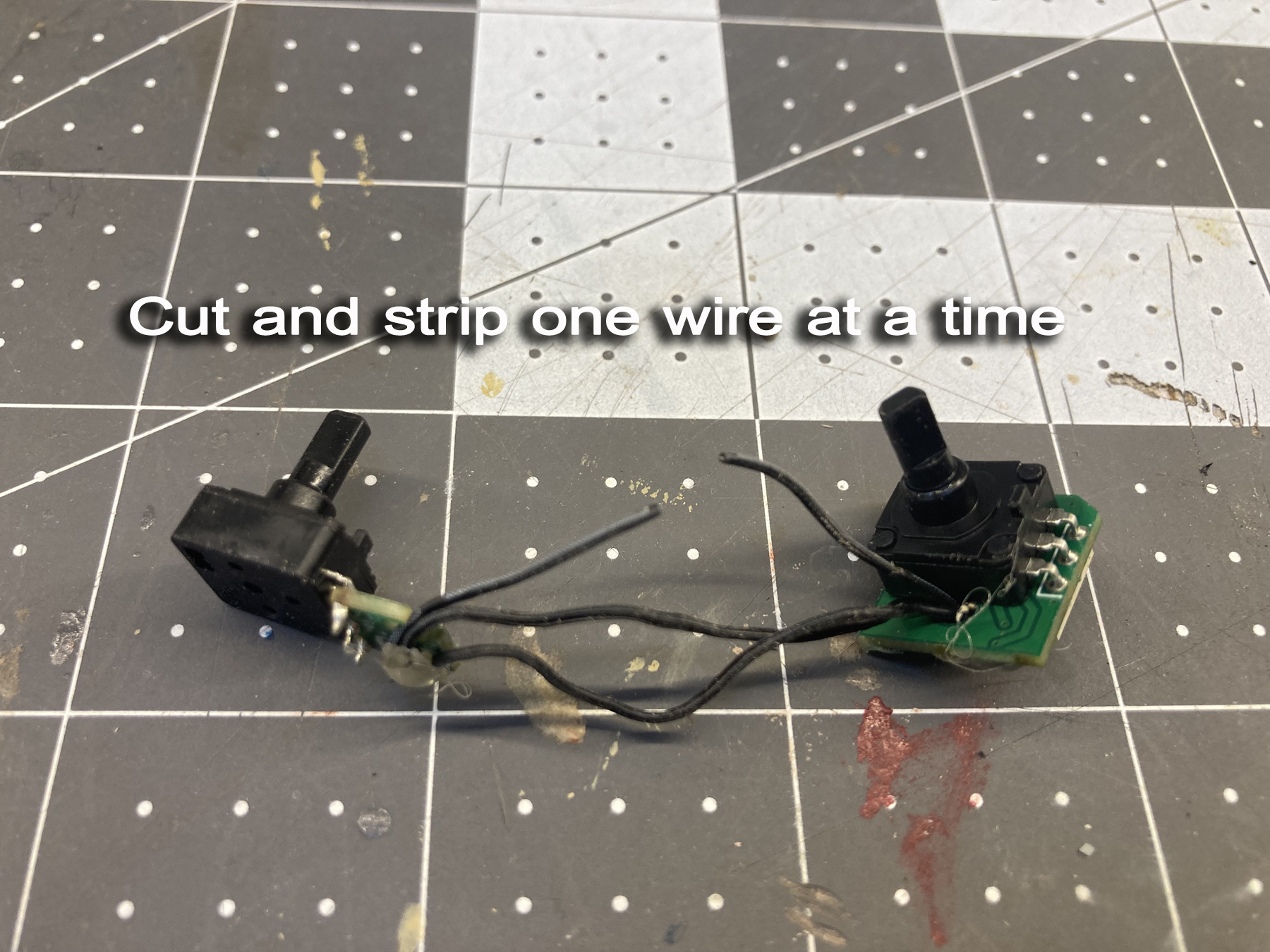
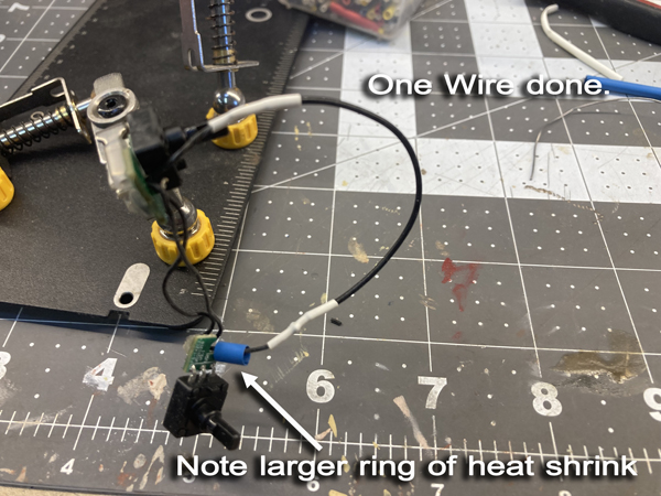 Complete extending the wires for the other two pot wires.
 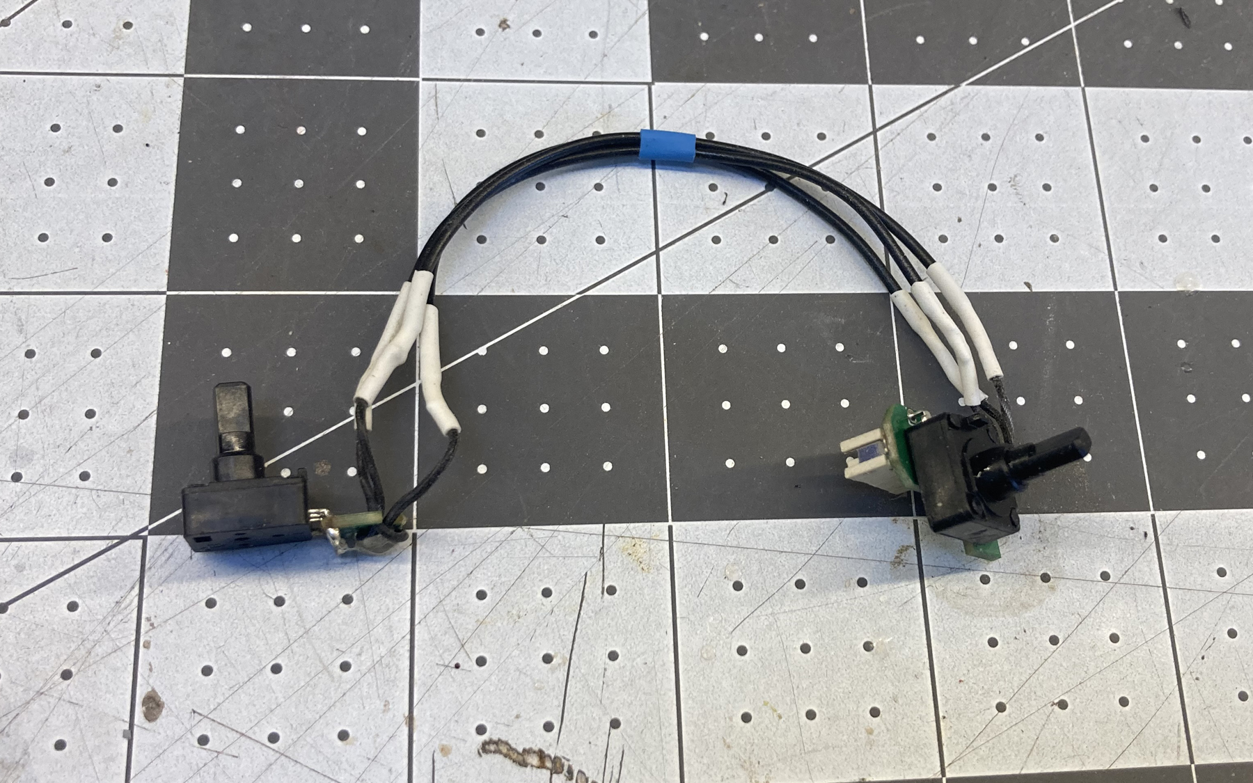 Using the # 51 drill bit, open the holes in the potentiometer
sadles. Also open the holes in the bezel mounting holes,
and the Center support with Hole mounting holes at either end of the
support. You don't have to open any holes on the inside face of
the bezel, just the four that on the side that will face out towards
you when the transmitter is assembled.
Using the # 51 drill bit, open the holes in the potentiometer
sadles. Also open the holes in the bezel mounting holes,
and the Center support with Hole mounting holes at either end of the
support. You don't have to open any holes on the inside face of
the bezel, just the four that on the side that will face out towards
you when the transmitter is assembled. 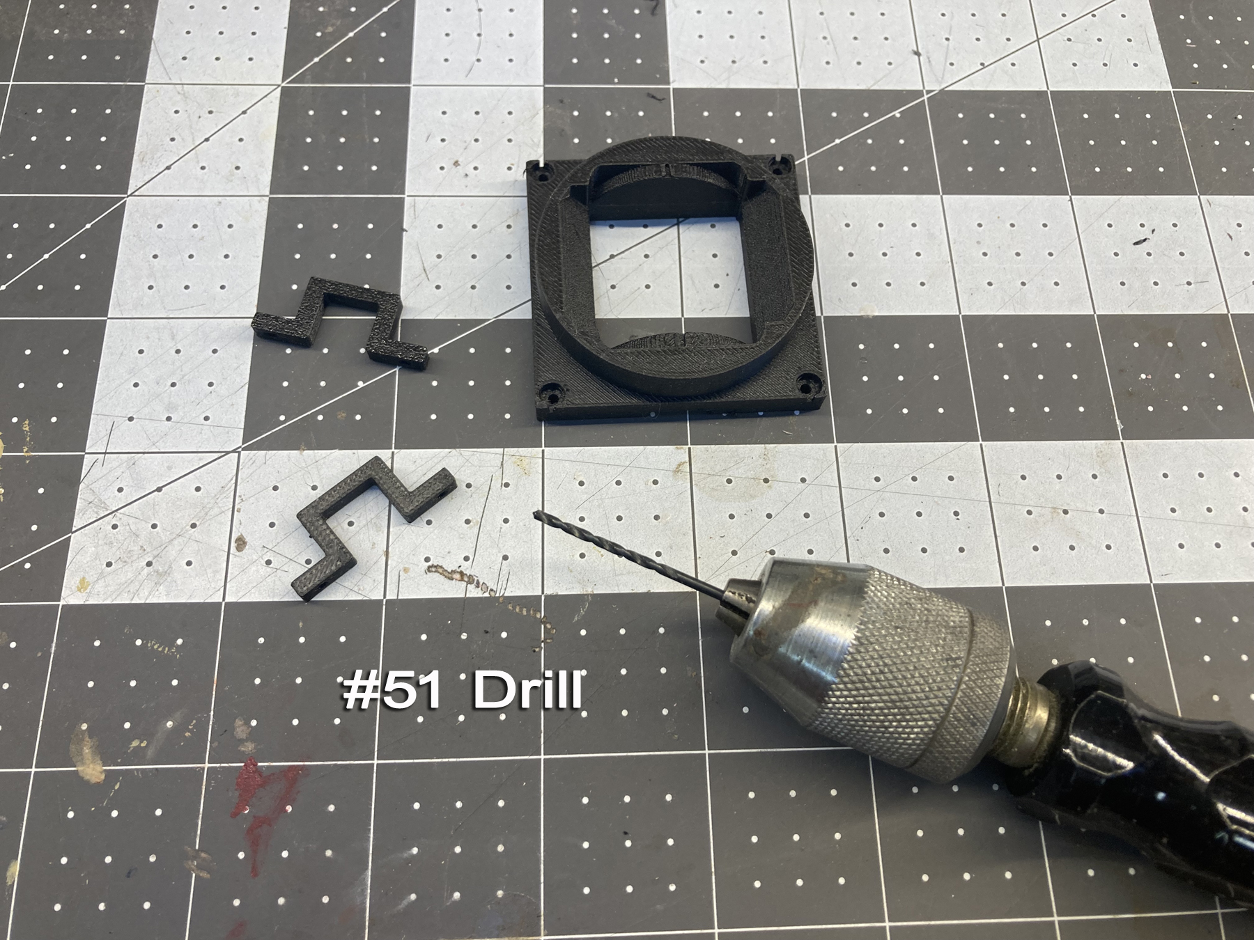 Using a 7/32" bit, clean out the round hole on the inside of the
two quadrants. It should be pretty close to size, but I like to
bore out to the final dimension due to variations in
printing. Make sure you bore from the large hole side, not
the narrow, smaller side.
Using a 7/32" bit, clean out the round hole on the inside of the
two quadrants. It should be pretty close to size, but I like to
bore out to the final dimension due to variations in
printing. Make sure you bore from the large hole side, not
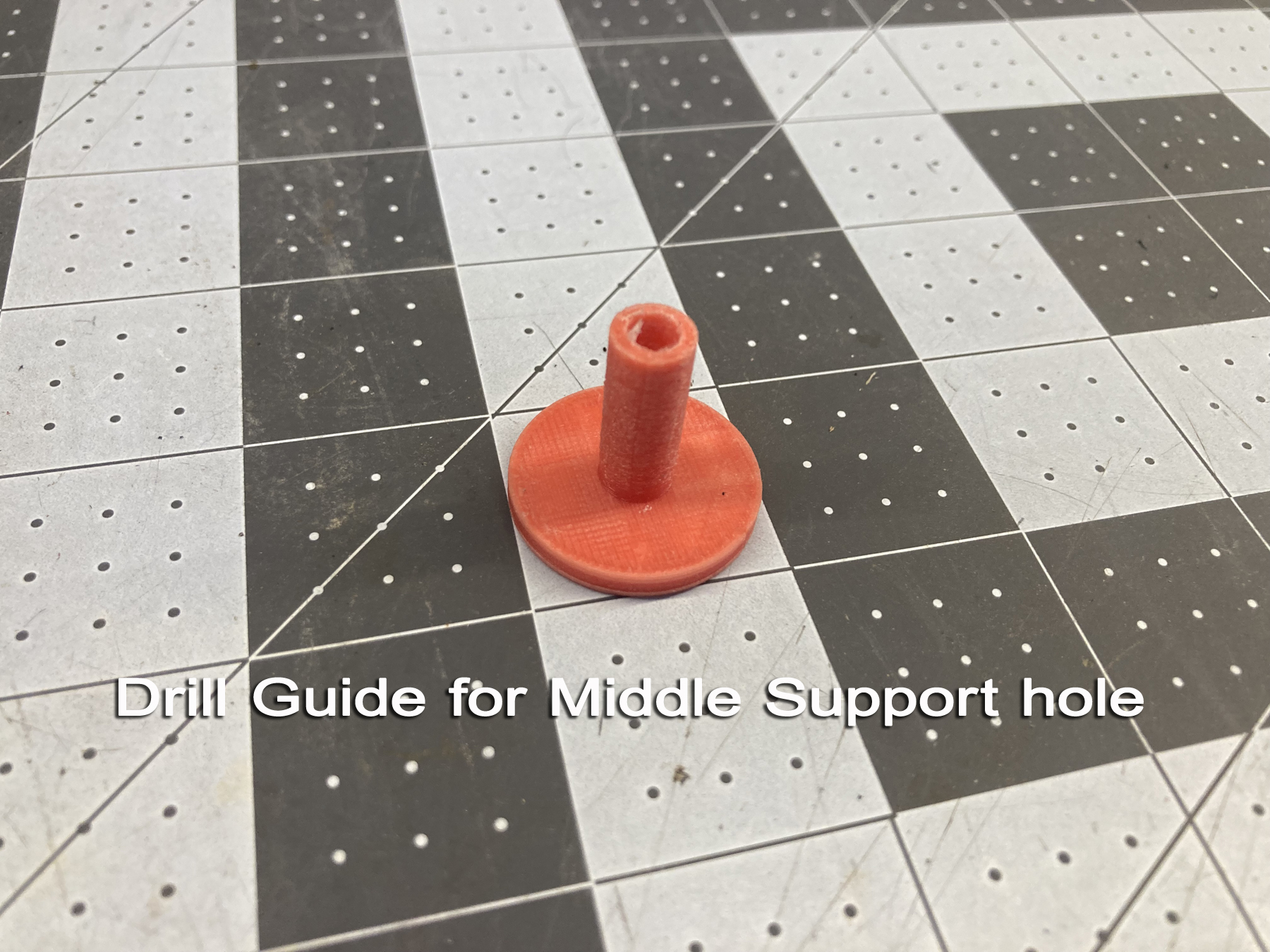
the narrow, smaller side.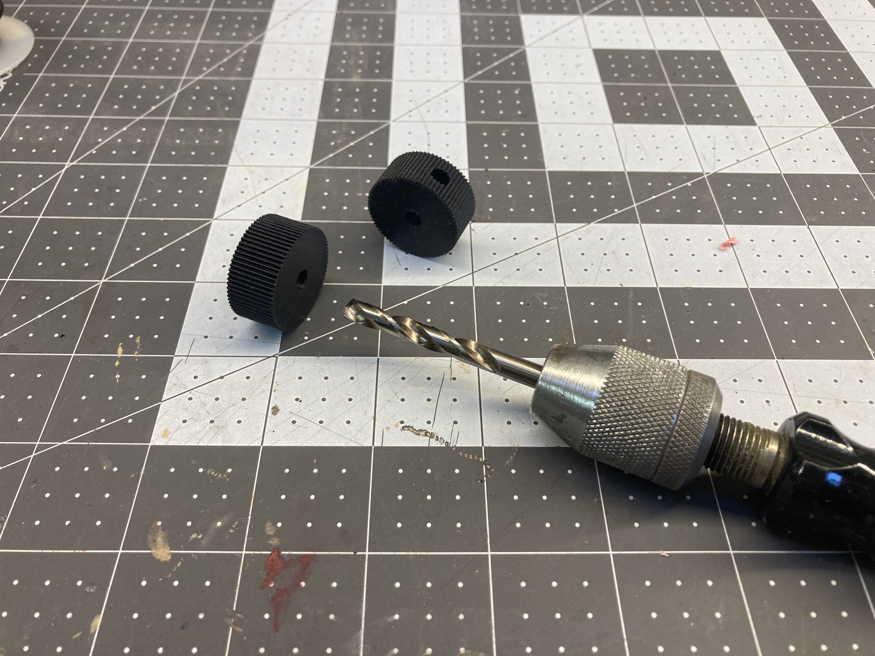 Using the 3/16" drill bit, clean out the hole in the middle
support
with hole part. If you have a drill press, use that,
otherwise use the drill guide that is included in the printing files.
Take your time, if the hole is not perpendicular the shaft will
be out of alignment, which can cause your quadrants to bind upon
assembly. If you need to, print a couple to make sure you
get thiis correct.
Using the 3/16" drill bit, clean out the hole in the middle
support
with hole part. If you have a drill press, use that,
otherwise use the drill guide that is included in the printing files.
Take your time, if the hole is not perpendicular the shaft will
be out of alignment, which can cause your quadrants to bind upon
assembly. If you need to, print a couple to make sure you
get thiis correct. 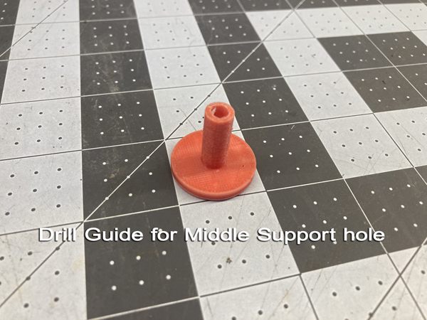 Slightly ease or chamer the end of the 7/32" tubing and insert it into
one of the quadrants. Insert into the quadrant until it bottoms
out. If you need to use a hammer to tap it in, rest the other
end of the tubing on a block of wood, and light strike the top of the
quadrant; avoid distoring the narrow opening that the potentiometer
will be inserted into. It should require a moderate amount ot of
force to seat
the tube.
Slightly ease or chamer the end of the 7/32" tubing and insert it into
one of the quadrants. Insert into the quadrant until it bottoms
out. If you need to use a hammer to tap it in, rest the other
end of the tubing on a block of wood, and light strike the top of the
quadrant; avoid distoring the narrow opening that the potentiometer
will be inserted into. It should require a moderate amount ot of
force to seat
the tube.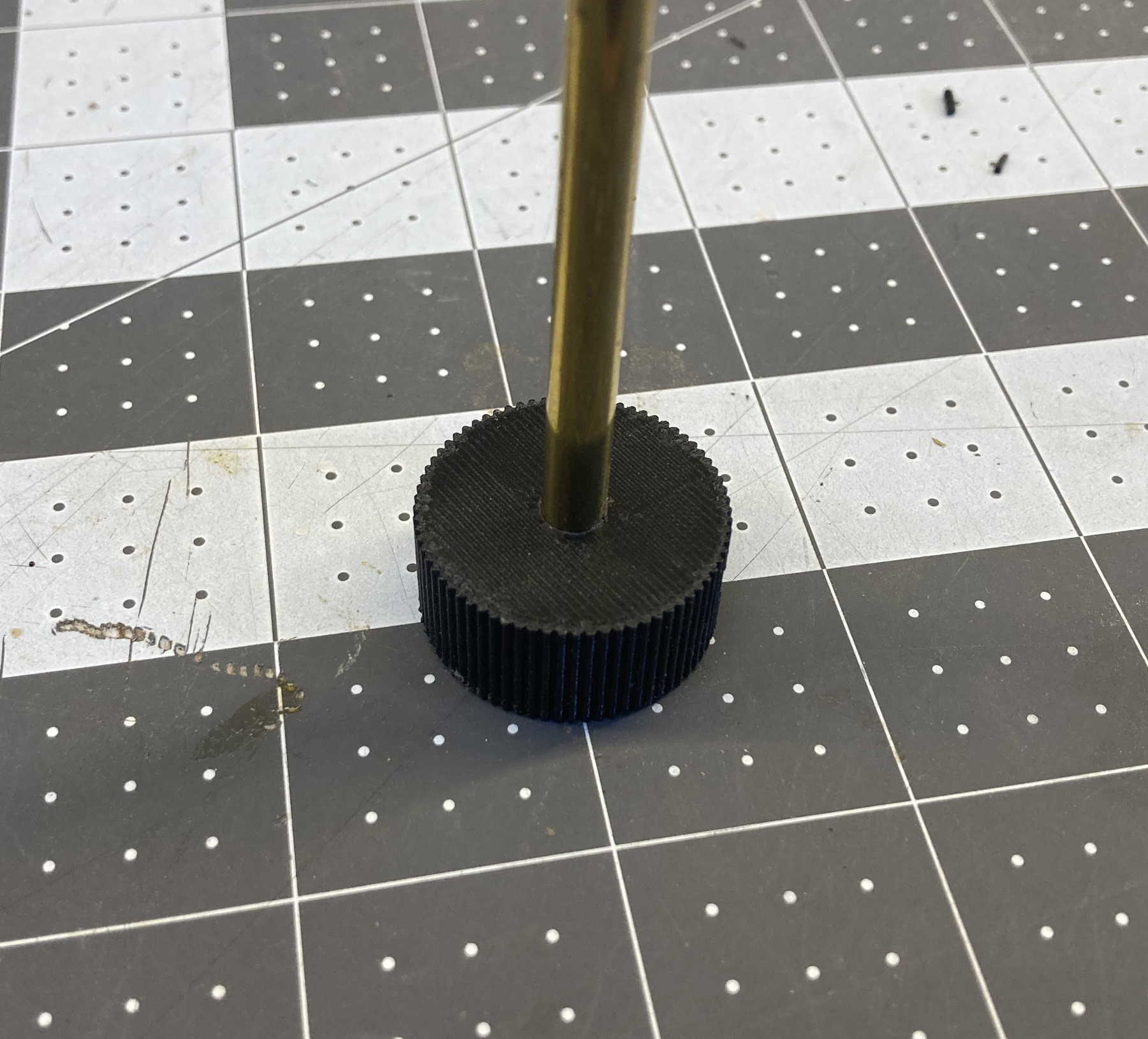 Using a razor saw, trim any tubing flush with the inner face of the
quadrant; sand or file as needed. Repeat this with the
other quadrant. Run the tip of a hobby knife around the inside of
the tube to de-burr it as needed.
Using a razor saw, trim any tubing flush with the inner face of the
quadrant; sand or file as needed. Repeat this with the
other quadrant. Run the tip of a hobby knife around the inside of
the tube to de-burr it as needed. 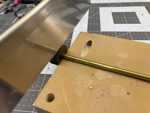 Sand or file the cut end of the tube flush with the face of the quadrant
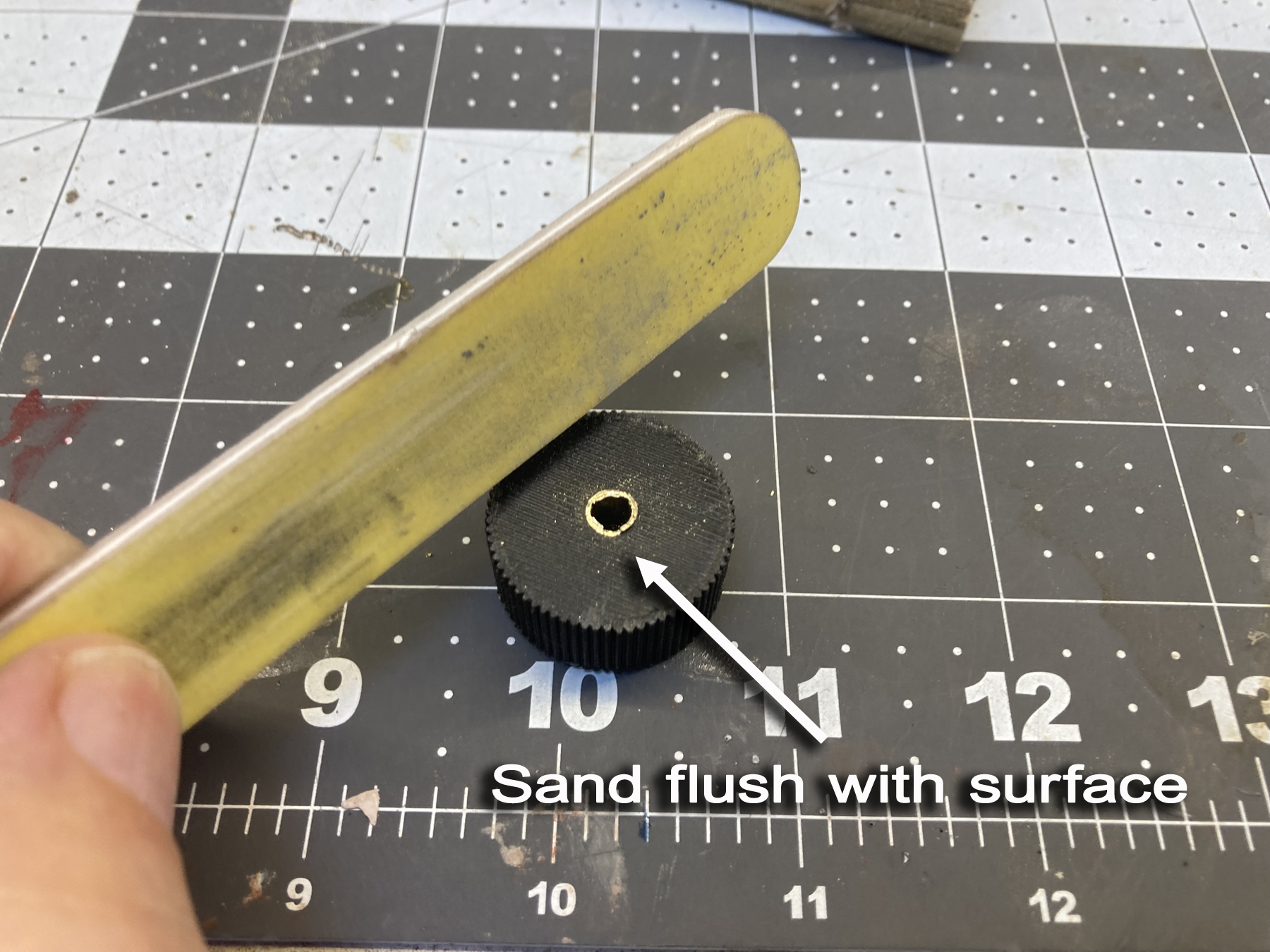 Ream the inside of the tube to remove any burr
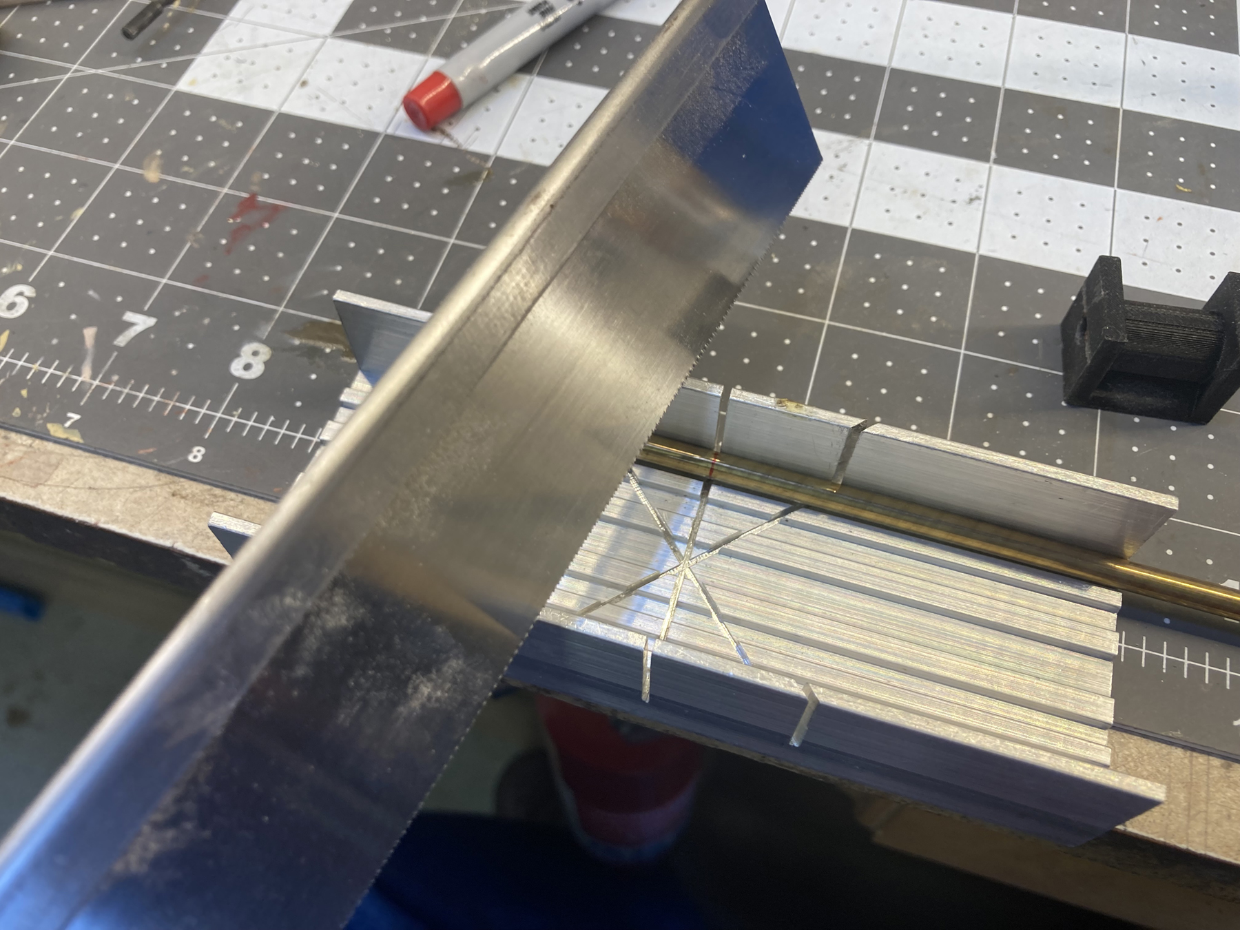
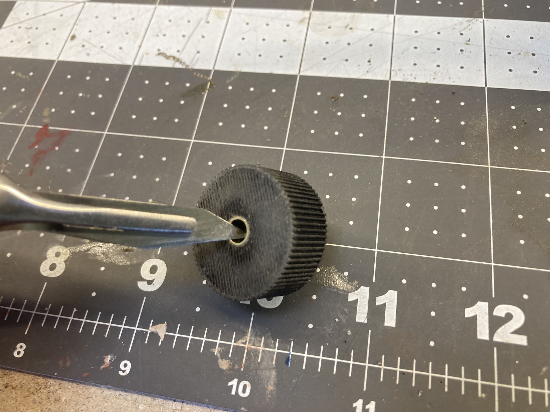 Use the Shaft cutting guide to mark out the length of the 3/16" solid
metal shaft. Mark it with a Sharpie, and trim to this line with a
razor saw (if brass) or whatever you have to cut stainless.
An alumimum miter box is handy for this step. Lightly sand
or chamfer the ends to remove any burrs. The shaft should
slide and rotate into the quadrant bushings without
binding.
Use the Shaft cutting guide to mark out the length of the 3/16" solid
metal shaft. Mark it with a Sharpie, and trim to this line with a
razor saw (if brass) or whatever you have to cut stainless.
An alumimum miter box is handy for this step. Lightly sand
or chamfer the ends to remove any burrs. The shaft should
slide and rotate into the quadrant bushings without
binding. 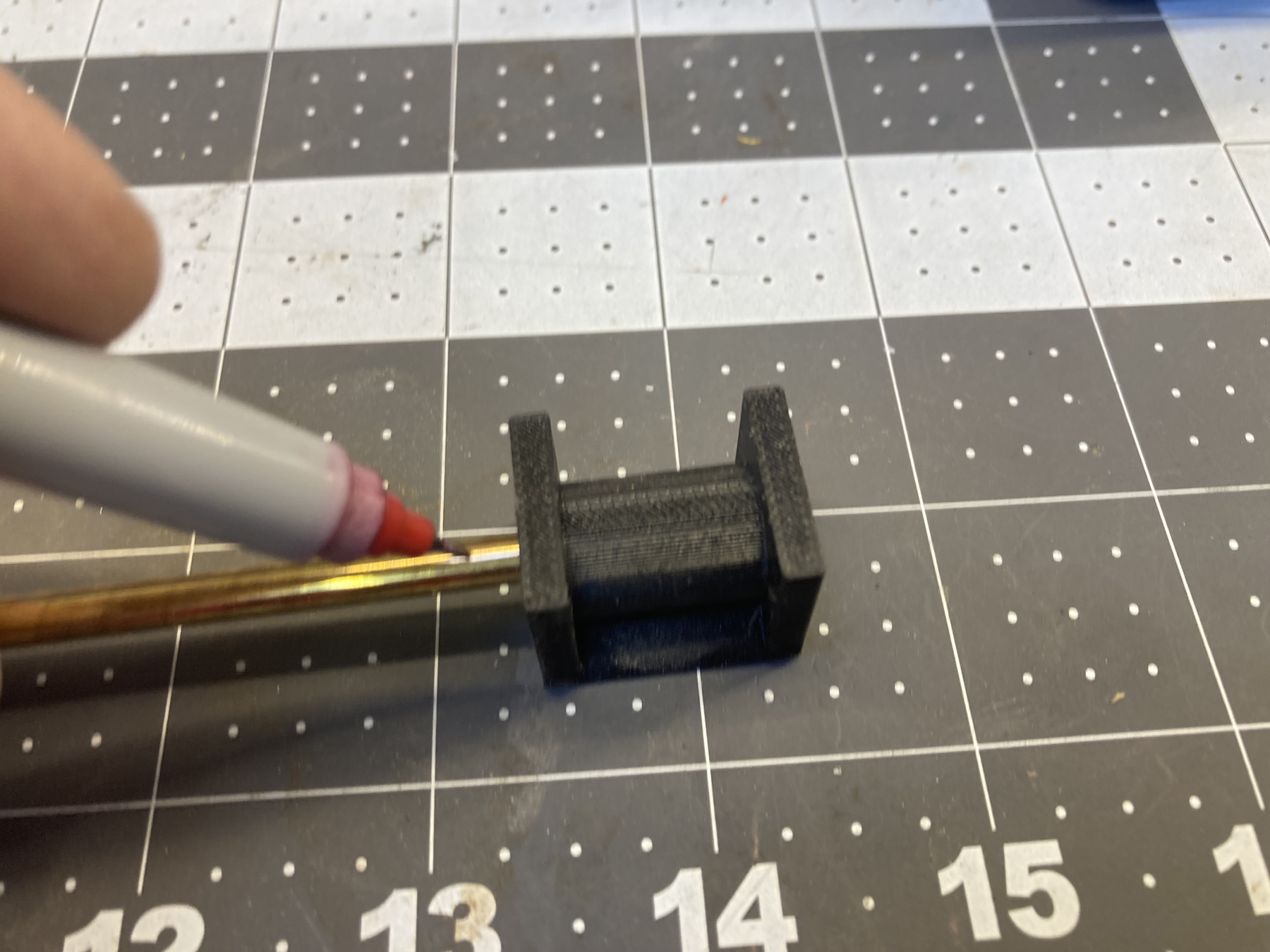
 Insert the shaft into the Middle Support with Hole. It may need
to be tapped into place. The center of the support should be in
the midde of the shaft, with both ends projecting out equally.
If the fit is loose, use a small amount of thin CA glue to hold it in
place. Be sure to let it fully cure and remove any
trace of the glue on the outsde of the shafts before proceeding.
Once the glue is dry, apply a small amount of Vaseline to the exposed
portions of the shafts. A microbrush is handy for this.
Insert the shaft into the Middle Support with Hole. It may need
to be tapped into place. The center of the support should be in
the midde of the shaft, with both ends projecting out equally.
If the fit is loose, use a small amount of thin CA glue to hold it in
place. Be sure to let it fully cure and remove any
trace of the glue on the outsde of the shafts before proceeding.
Once the glue is dry, apply a small amount of Vaseline to the exposed
portions of the shafts. A microbrush is handy for this. 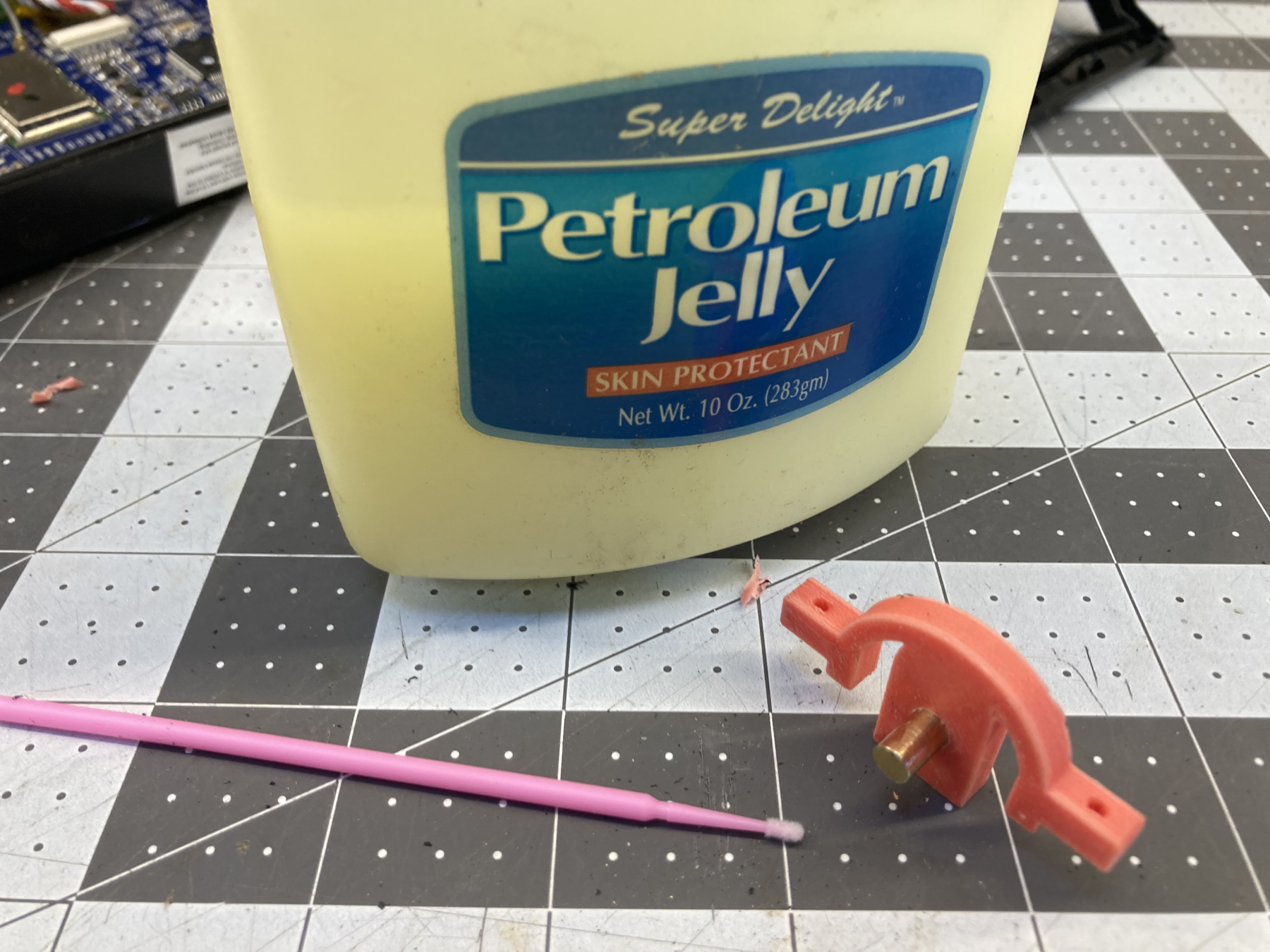 While you have the 3/16" drill out, clean out the holes on the side of
the quadrants where the throttle handle supports are attached to
the quadrants. Also clean out the holes in the throttle
handles. Use your 1/8" drill to clean out the holes on the
side of the throttle handles if you will be using the optional magnets.
Put both quadrants on either side of the Middle Support with
Hole. The hole for the throttle handle supports should be on the
radiused side of the support
Check for any binding, the quadrants should rotate smoothly.
While you have the 3/16" drill out, clean out the holes on the side of
the quadrants where the throttle handle supports are attached to
the quadrants. Also clean out the holes in the throttle
handles. Use your 1/8" drill to clean out the holes on the
side of the throttle handles if you will be using the optional magnets.
Put both quadrants on either side of the Middle Support with
Hole. The hole for the throttle handle supports should be on the
radiused side of the support
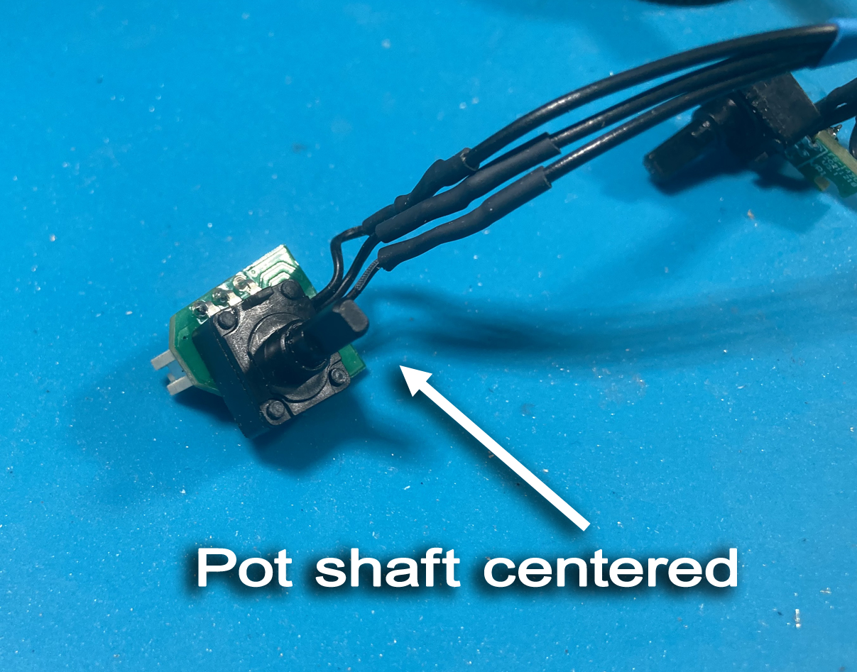
Check for any binding, the quadrants should rotate smoothly.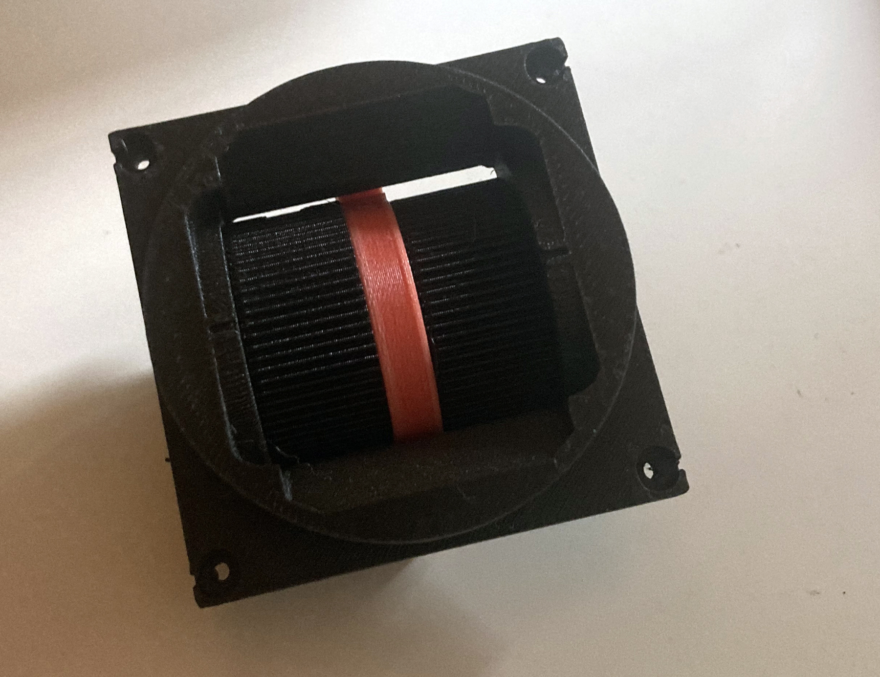 Take your two potentitomers, and center
their shafts by rotating them
one way and other until you find the center of rotation. They
should have about 100 degrees of swing, give or take, on either side to
work properly. When you have their shafts centered,
posistion the circuit boards to face inside the radio case (and away
from the throttle handle support holes)
Take your two potentitomers, and center
their shafts by rotating them
one way and other until you find the center of rotation. They
should have about 100 degrees of swing, give or take, on either side to
work properly. When you have their shafts centered,
posistion the circuit boards to face inside the radio case (and away
from the throttle handle support holes)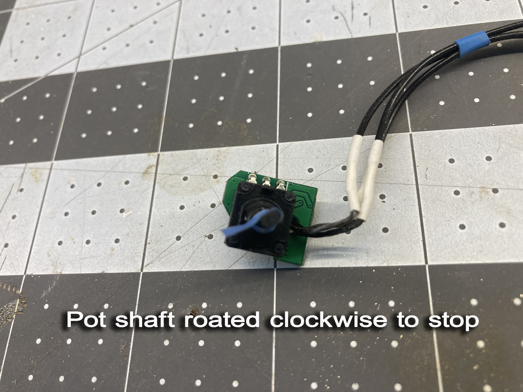 .
. Insert the potentiometer with the larger
circuit board on the left side
of the quadrant assembly. Insert the other on the right
side. Run the wires abovc the assembly, which will be the
top of the radio case. Note that it will seat full on the first step of
the potentiometer shaft, but there will be two steps exposed.
Insert the potentiometer with the larger
circuit board on the left side
of the quadrant assembly. Insert the other on the right
side. Run the wires abovc the assembly, which will be the
top of the radio case. Note that it will seat full on the first step of
the potentiometer shaft, but there will be two steps exposed. 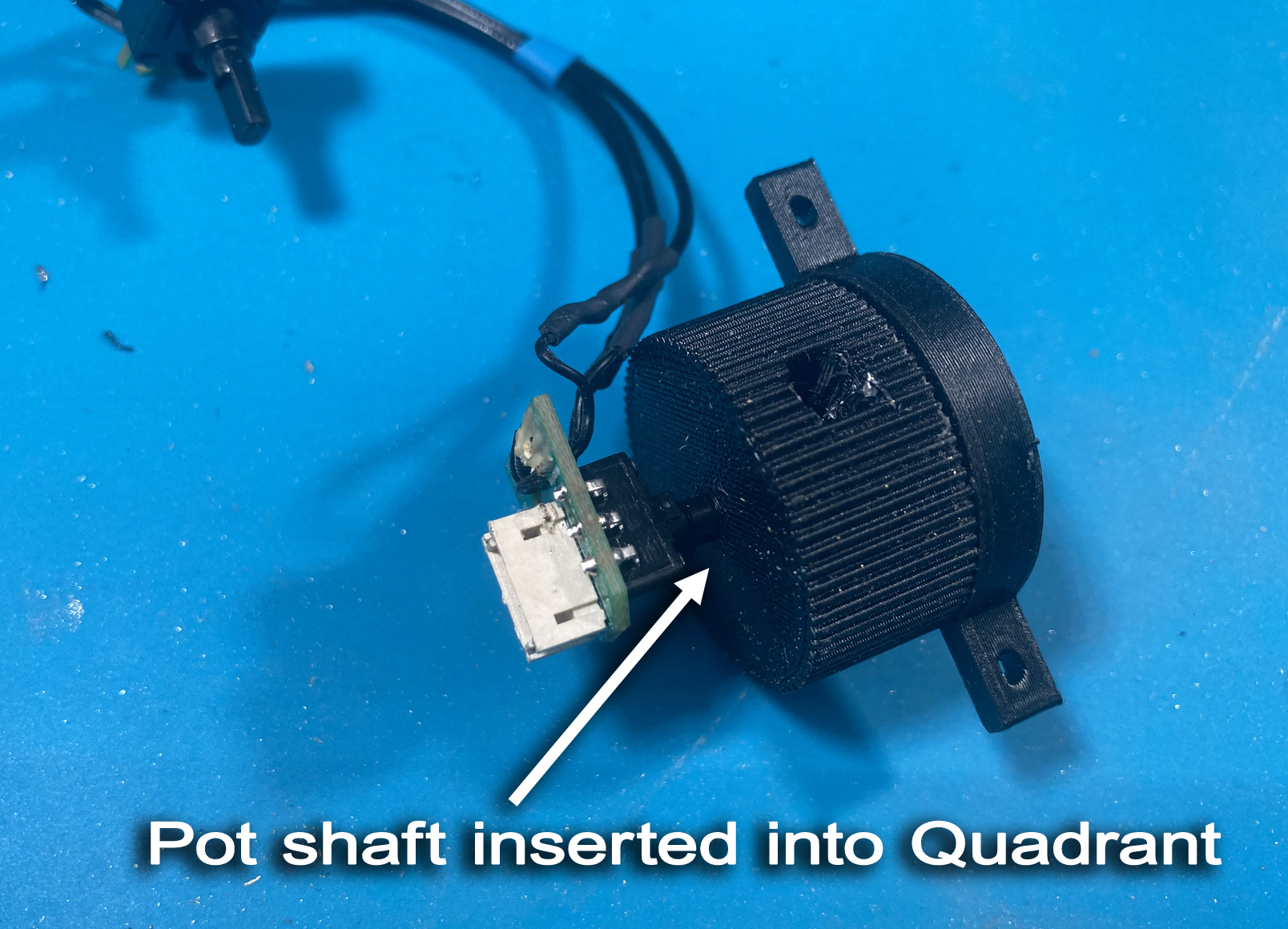 Put the assembly into the bezel, making sure that the potentiometers
seat into the slots provided in the bezel
Put the assembly into the bezel, making sure that the potentiometers
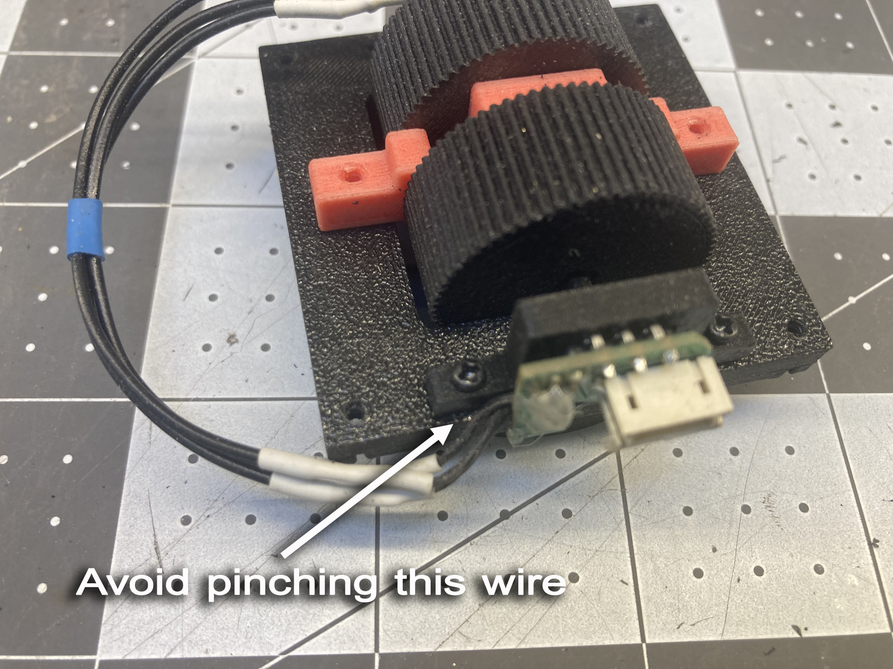
seat into the slots provided in the bezel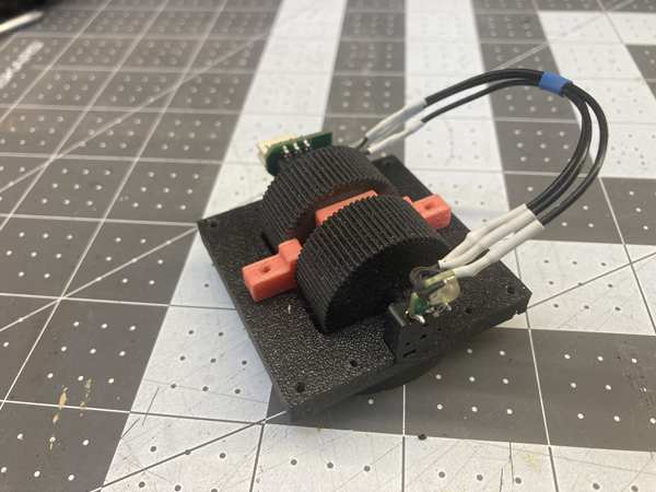 Put the Saddles over the potentiometers, making sure you clear the
wires. I found on the left side it is good to put the small
1.7mm x 8mm screw in the upper hole first, and then place it into
place, as the wiring harness can get in the way. Be very careful
not to trap or damage the wiring harness when screwing the saddles into
place.
Put the Saddles over the potentiometers, making sure you clear the
wires. I found on the left side it is good to put the small
1.7mm x 8mm screw in the upper hole first, and then place it into
place, as the wiring harness can get in the way. Be very careful
not to trap or damage the wiring harness when screwing the saddles into
place. 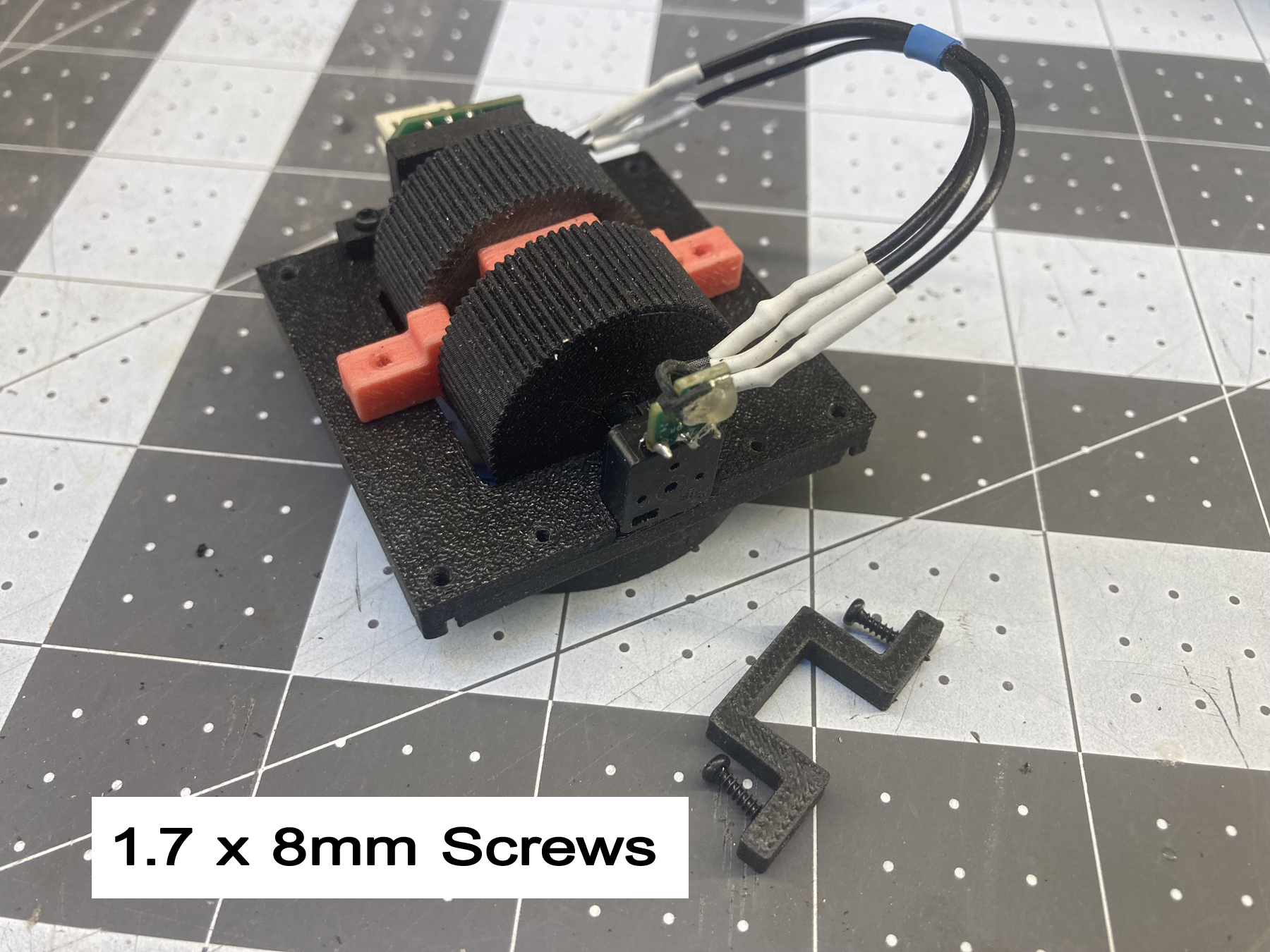
 Depending on the tolerances of you printer, the saddles may not fully
seat, and that is Ok. They just have to prevent the
potentiomers from moving. Insert the solid aluminum throttle sticks
into the quadrants. These should be a tight fit, so you may
have to press a bit. If it is loose, you can use a small drop of
medium viscosity CA cement to lock them into place
Depending on the tolerances of you printer, the saddles may not fully
seat, and that is Ok. They just have to prevent the
potentiomers from moving. Insert the solid aluminum throttle sticks
into the quadrants. These should be a tight fit, so you may
have to press a bit. If it is loose, you can use a small drop of
medium viscosity CA cement to lock them into place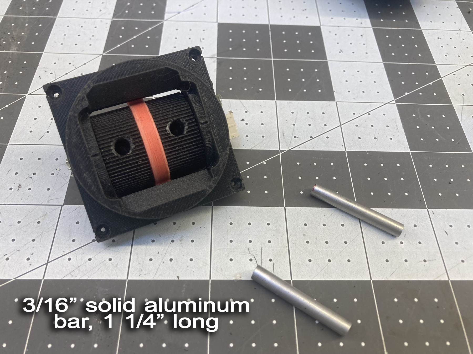 This is a good place to check to
make sure your potentiometer shafts were properly oriented. You
should be able to push the sticks up and down to their full
travel. If you cannot, you will need to disassemble and
re-orient the pot shafts. Prepare the throttle handles.
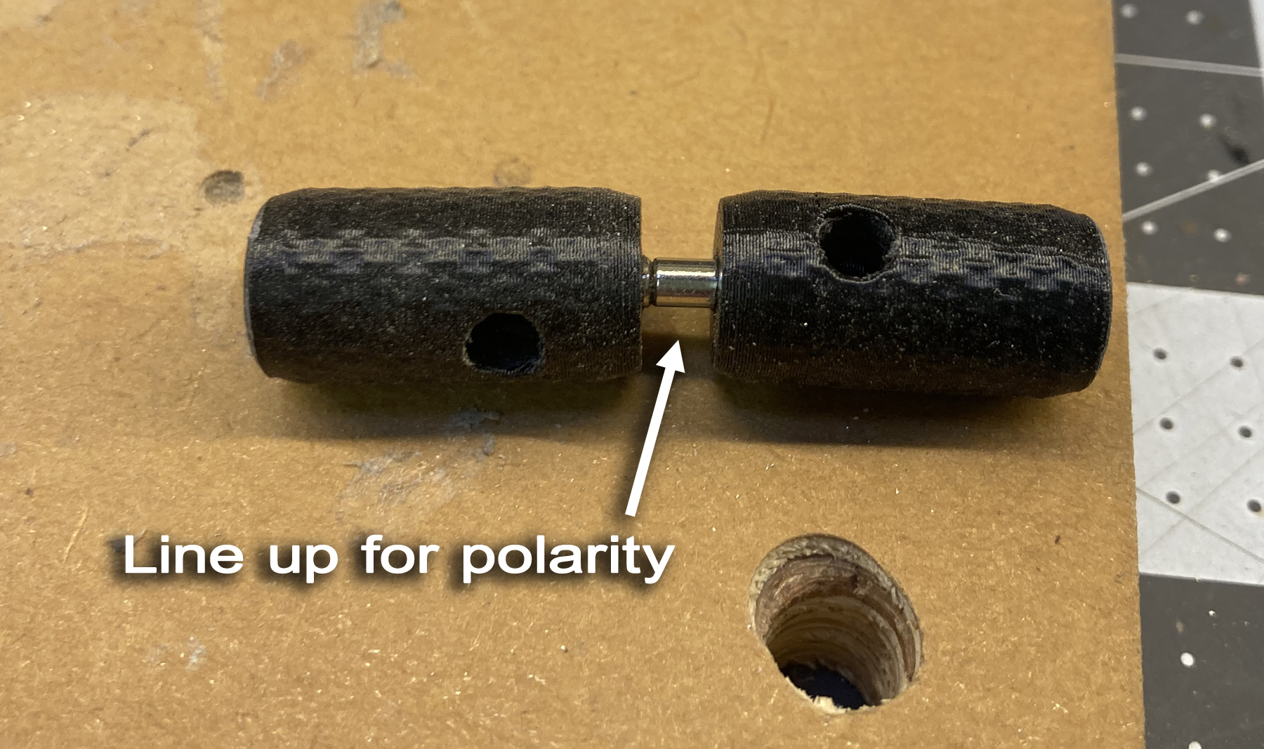
If you want to have rare earth magents installed so the sticks can move
together, insert a 1/8" diamter by 1/4" long rare earth magnet into the
hole at the end of one handle. It should be a press
fit. Then take the other magnet and let it attack to the
first; this ensures that you don't have the polarization
reversed. Then insert this into the second throttle handle
and seat it. The magnets will project slightly from each
throttle handle. If you find that they require more force
that you want to disengage, then you can use shorter magnets and set
them flush with the end of the handle. You can experiment to find
the best amount for your needs.
This is a good place to check to
make sure your potentiometer shafts were properly oriented. You
should be able to push the sticks up and down to their full
travel. If you cannot, you will need to disassemble and
re-orient the pot shafts. Prepare the throttle handles.
If you want to have rare earth magents installed so the sticks can move
together, insert a 1/8" diamter by 1/4" long rare earth magnet into the
hole at the end of one handle. It should be a press
fit. Then take the other magnet and let it attack to the
first; this ensures that you don't have the polarization
reversed. Then insert this into the second throttle handle
and seat it. The magnets will project slightly from each
throttle handle. If you find that they require more force
that you want to disengage, then you can use shorter magnets and set
them flush with the end of the handle. You can experiment to find
the best amount for your needs. 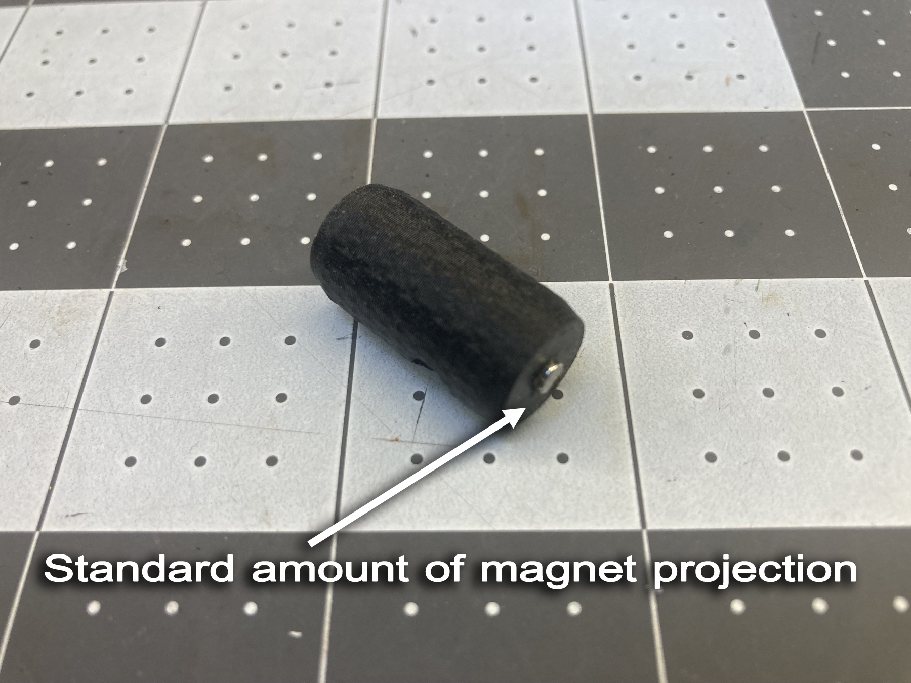
 Insert the throttle handles onto the stick
shafts. Your Gimbal is now assembled
Insert the throttle handles onto the stick
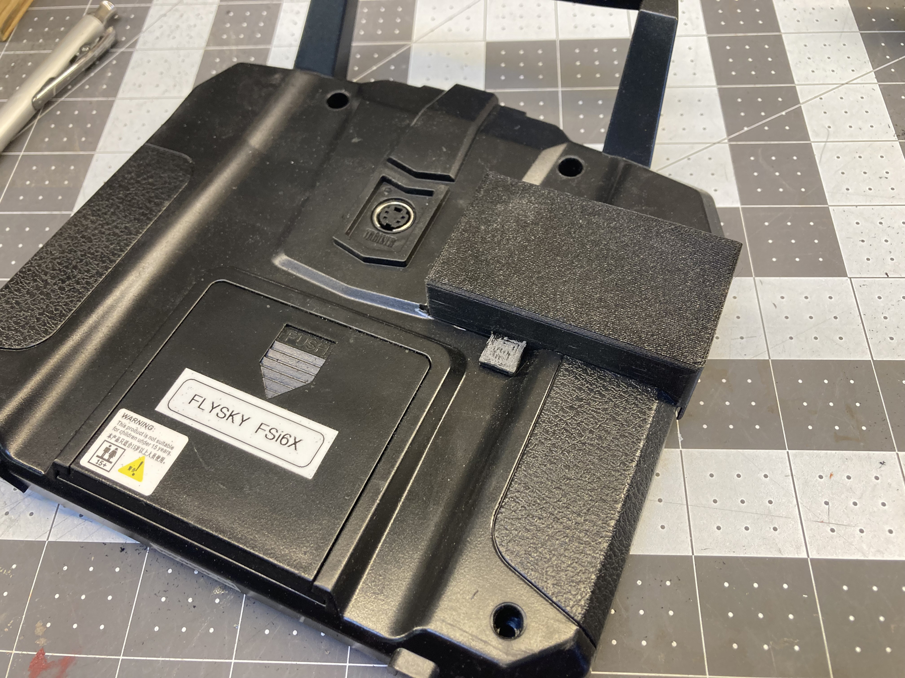
shafts. Your Gimbal is now assembled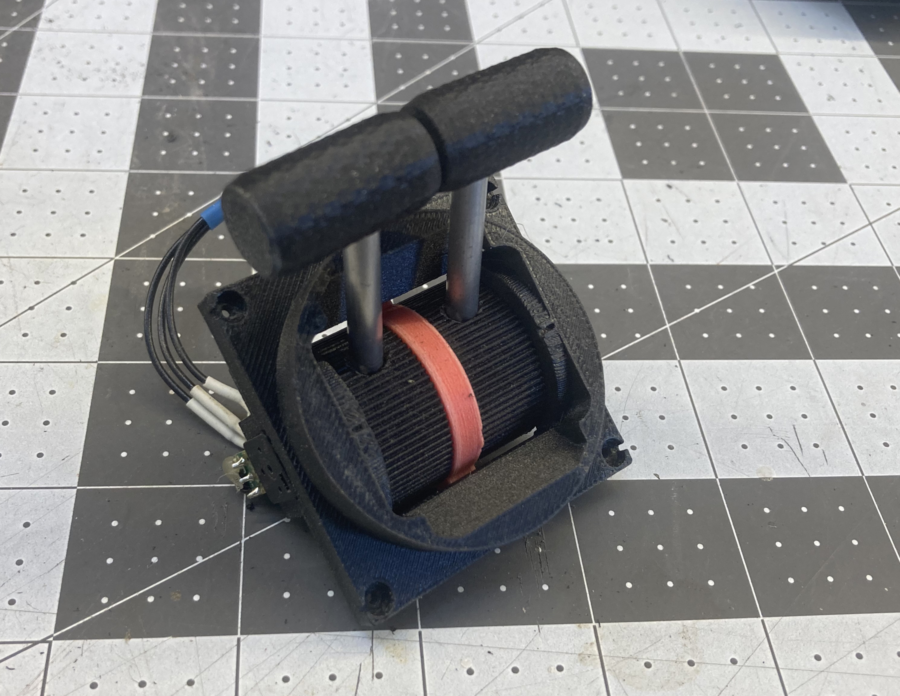 Now insert the bezel assembly into the radio. You can feed in one
of the throttle handles first; it will fit when completly
assembled. If you find it easier to do so, you can remove one or
both of the throttle handles. When the gimbal is seated on
the four posts inside the radio case, you should feel it seat into
place. Use 4 2.3mm x 10mm screws to attach the
gimbal to the case. Again, no need to over-torque these
screws. Plug the gimbal plug back into place.
Now insert the bezel assembly into the radio. You can feed in one
of the throttle handles first; it will fit when completly
assembled. If you find it easier to do so, you can remove one or
both of the throttle handles. When the gimbal is seated on
the four posts inside the radio case, you should feel it seat into
place. Use 4 2.3mm x 10mm screws to attach the
gimbal to the case. Again, no need to over-torque these
screws. Plug the gimbal plug back into place.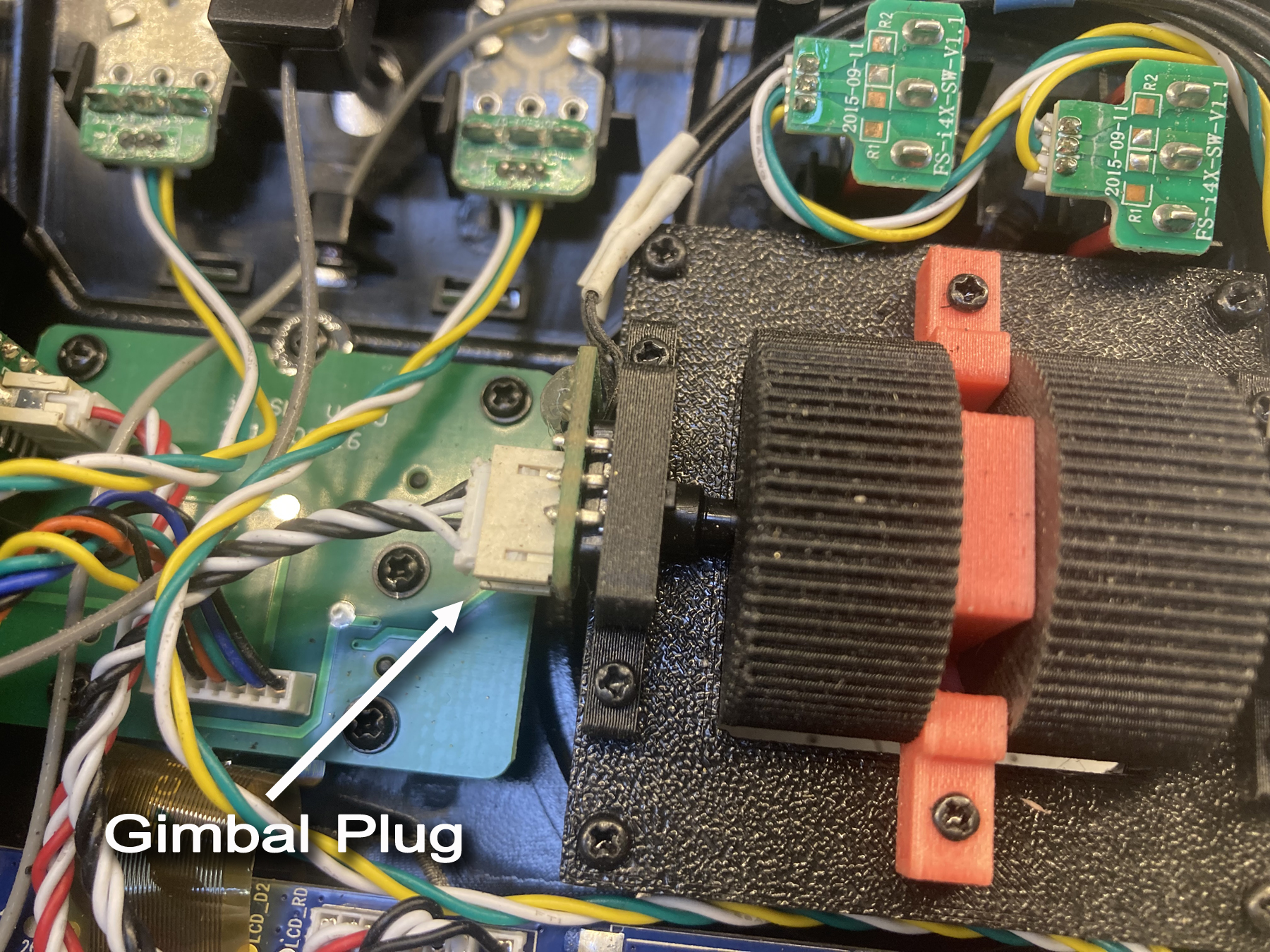
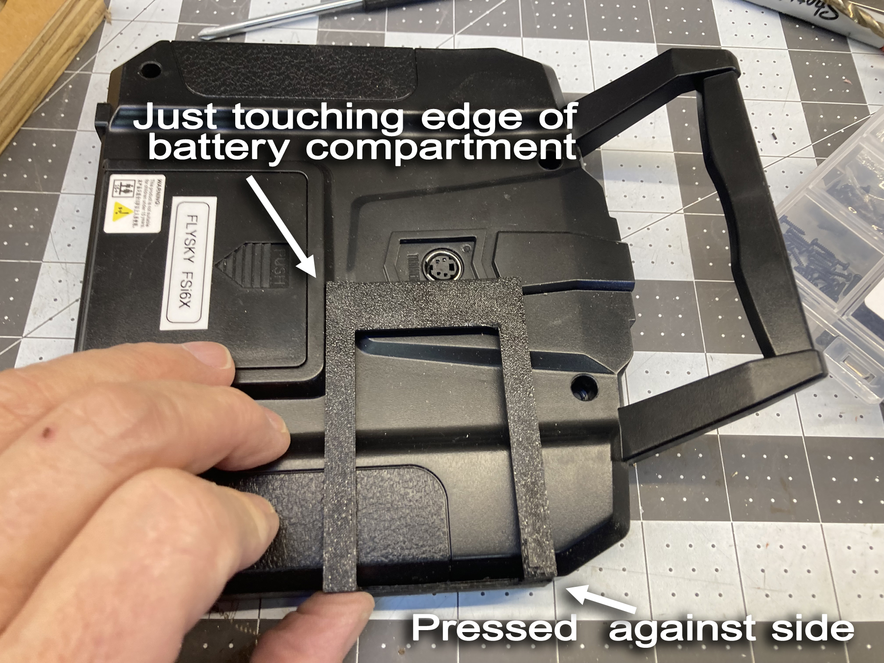
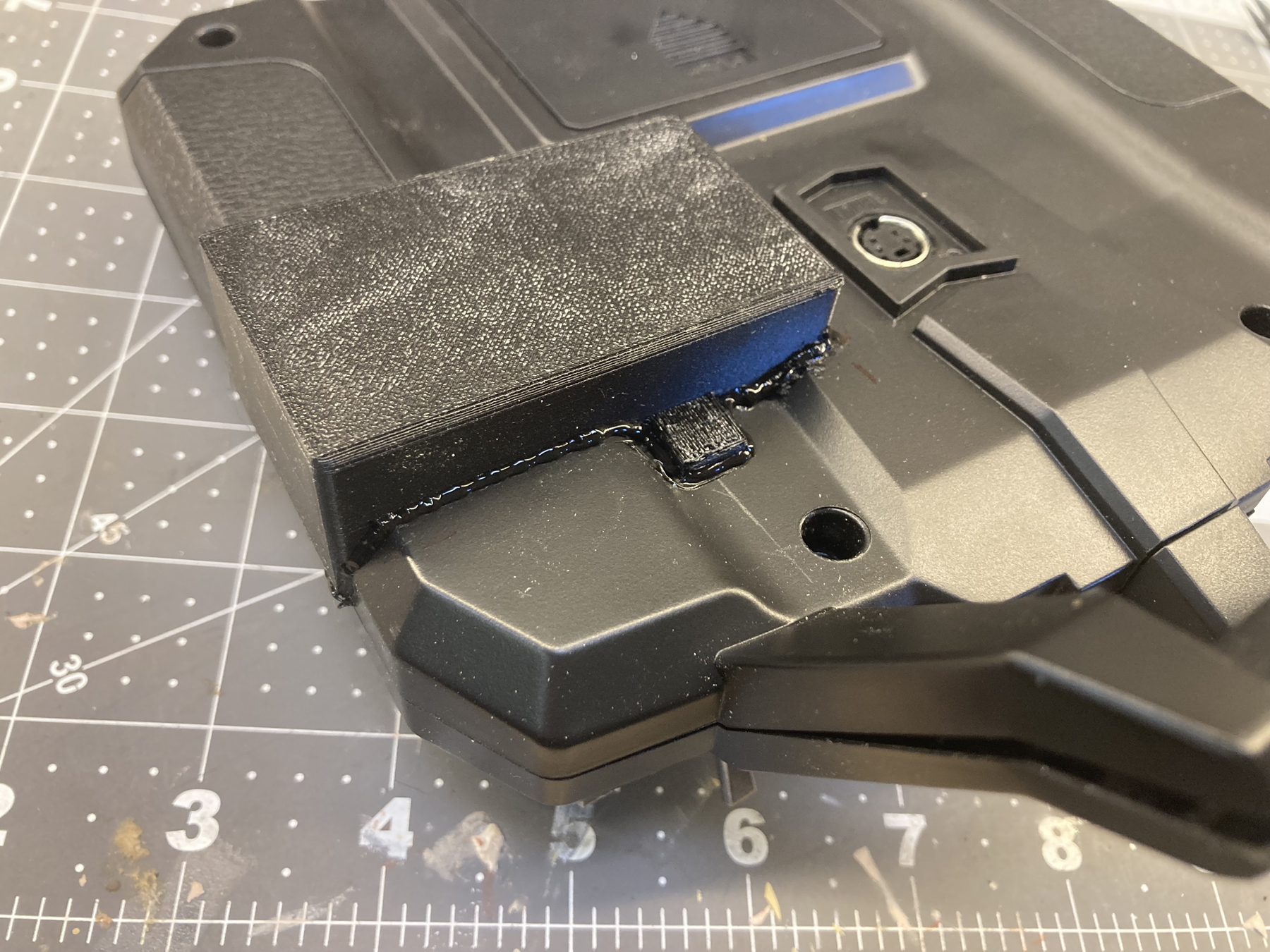
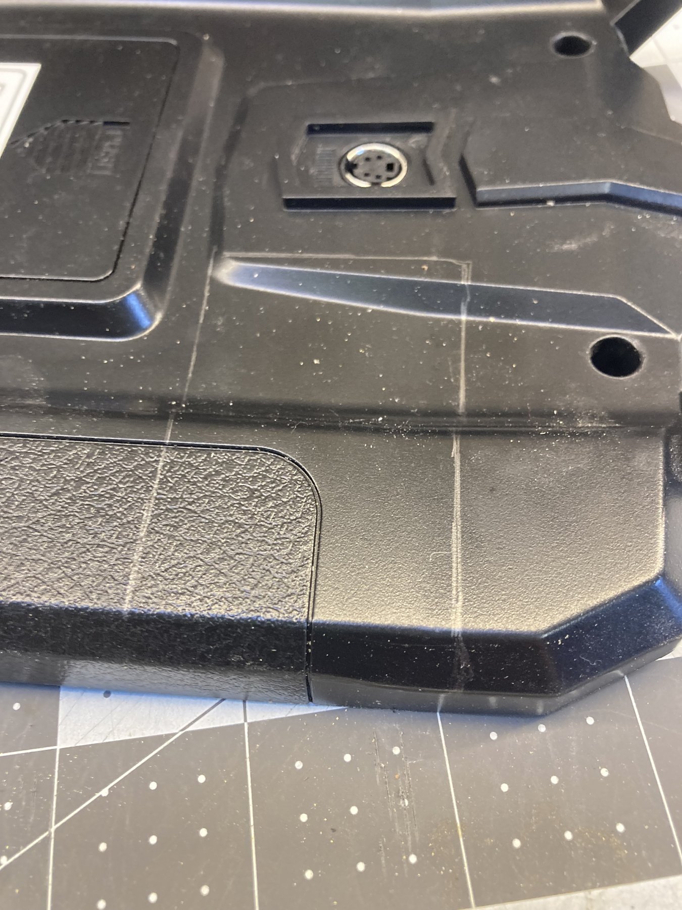 Cut the hole slightly inside the
markings. You can use a variety of ways to cut the cover;
razor saw, chain drill a series of holes, a dremel tool equiped with a
saw blade, whatever is safe and comfortable for you to do, With
the undersized rough hole cut, sand to fit.
Check with the printed cover often; you are
aiming for a nice friction fit. the back cover will sit on the
two "ears" and the lip at the rear.
Cut the hole slightly inside the
markings. You can use a variety of ways to cut the cover;
razor saw, chain drill a series of holes, a dremel tool equiped with a
saw blade, whatever is safe and comfortable for you to do, With
the undersized rough hole cut, sand to fit.
Check with the printed cover often; you are
aiming for a nice friction fit. the back cover will sit on the
two "ears" and the lip at the rear. 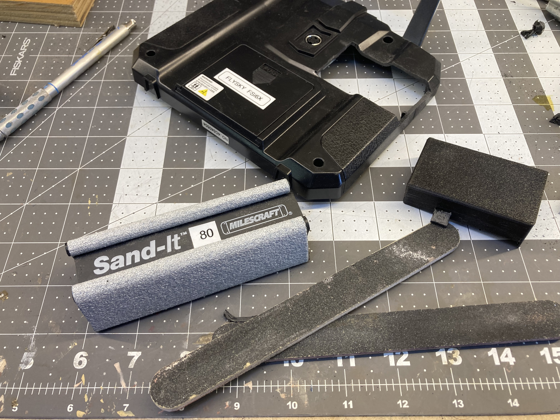

Return to Warship Models Underway
1657
 Please write me with your comments!
This page maintained by Kurt Greiner. Version 1 10/25