
Several basic things need to be considered before embarking on a major project like this:
Can you risk ruining your radio Tx and have to replace it. Can you tolerate your radio being "down" for a week of evenings while you complete the project?
Tools and Materials Needed:
I thought long and hard on the first two points (as should you) and decided to take the risk. The Robbe ship radio with its nice twin throttles would be great to have, but is a bit beyond me. I had converted my Fletcher DD to a Gearing FRAM DD (Gallery 50) and had added twin motor speed controls and motors in the process. I wanted to be able to "parallel-park" the ship using differential-throttle control and rudder. Running both motors off a single joystick did not allow full forward on one motor and full reverse on the other to allow the flexibility in maneuverability that full differential throttles offered. It had to be just like the real thing!
The tools and terminology I had accumulated over the years, so the decision was made and the tools were hopping about the workbench anxious to get started. We began.
I had decided to keep the aileron control on the right side of the Tx and make the left side into the twin throttles as the motors speed controls were already programmed to the ranges of travel for the rudder and throttle functions of the joystick on that side ("rudder" was left motor, "throttle" was right motor).
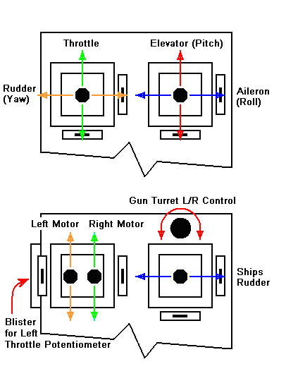
To ease the comparison I use aircraft function names in this How-To article for stick functions. Most of us are familiar with them as they are pretty standard. Here is a graphic and a table of how I changed the functions:
| Aircraft Function (WAS) | Use for my Gearing FRAM DD (IS NOW) |
| Aileron (Roll) | Ships Rudder |
| Elevator (Pitch) | Gun Turret L/R Control |
| Throttle Right Motor | FWD/REV speed control |
| Rudder (Yaw) Left Motor | FWD/REV speed control |
I removed and safely stored the Tx batteries to minimize the risk of fire (charged batteries can be dangerous if not handled and stored properly).
Next I removed the screws that hold on the back cover (I bagged everything in sandwich bags as things came apart.)
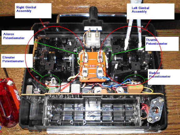
Once the back was off I photographed all the wiring connections to ensure that I got things hooked back up the right way when the project was done.
NOTE - BE ESPECIALLY CAREFUL WHEN POKING AROUND INSIDE THE Tx SO THAT YOU DON'T TOUCH ANY OF THE ADJUSTABLE PARTS, OR BEND THINGS ABOUT AND CAUSE SHORT CIRCUITS. Not your cup of tea? Stop, put the cover back on and purchase a twin throttle radio. No shame in that. I wish I had one!!!
I removed the screws from items inside the case, one by one, knowing that all the Tx parts would have to come out of the case. The screws that hold the joystick Gimbals in place were removed from the front of the case.
The new, left, throttle potentiometer would need to extend outside the left side of the case a little ways since the radio case is very compact. Some cutting on the case would need to be done to make room for the new, relocated, potentiometer. A "blister" cover would be fabricated to cover the potentiometer and otherwise protect it. To me this is acceptable to have the appearance suffer a bit for the additional controllability that the twin-throttle mod offers the Gearing DD.
Once all the screw were removed and bagged, I coaxed all the parts out of the Tx case and put them safely in a protective box (soda or beer flat).
Each potentiometer was marked with a piece of tape as to its function (aileron (L\R), elevator, rudder and throttle. The aileron and elevator controls were on the joystick of the right Gimbal Assy, rudder and throttle were on the joystick of the left Gimbal Assy.
Each potentiometer was marked as to the color of the wire that are connected to each of the terminals for replacement later. Yes, I de-soldered all the wires on the potentiometers after marking them so that the Gimbal Assy's could be completely removed from the Tx wiring.
Early on, I had decided use the elevator gimbal of the right Gimbal Assy as the aileron function because it would be easier to lock the stick movement in the L/R direction than the front back direction. In the end the right Gimbal Assy would be rotated 90 degrees when reinstalling it and the aileron potentiometer was installed into the elevator gimbal and the aileron wires were connected to it. In short the elevator gimbal became the aileron (L/R) gimbal and the aileron gimbal was completely removed and used later in the twin throttle mod of the left Gimbal Assy.
The now-orphaned elevator potentiometer is to be mounted on the top of the Tx case with a knob to be used to control the gun turrets in Azimuth (they will be mechanically linked to elevate as they turn).
Before disassembling any of the Gimbal Assy parts I photographed the Gimbal Assy from several different angles to aid in reassembly. I also took photos as each part as it came off and was laid-out in relation to where it had been installed.
The modification of the right Gimbal Assy for the ships rudder (aileron) was fairly simple to do (see the pictures) and I did it first to get comfortable before tackling the heavy mods needed to change the left Gimbal Assy into the twin throttle set-up. Once the right Gimbal Assy was completely disassembled, the aileron gimbal and potentiometer where removed and set aside. The Elevator gimbal potentiometer was removed and the aileron potentiometer was reinstalled in its place. The joystick was locked into the center position for the old "aileron" control (L/R) motion by using screws and super glue to immobilize it. The stick now moved only one direction. Now having a nice one-axis of movement Gimbal Assy for the ships rudder, I reinstalled the Right Gimbal Assy, rotating it so that the old elevator direction of travel is now in the aileron direction and will control the ships rudder. Next I preceded to the left Gimbal Assy and the actual meat of the project.
I choose to use the original aileron gimbal (left-right motion) that was set aside from the from the right Gimbal Assy (that was set aside in the steps above), and its counter part in the left Gimbal Assy (Rudder, left-right motion), as the gimbals to use for the twin throttles. I did this because it seemed like it would be easier to attach the sticks from the donor- radio to them and would result in an easier modifications to create the dual throttle gimbal Assy.
The left Gimbal Assy was completely disassembled. The throttle gimbal was sent to the spare parts box. The sticks from the donor radio were removed from the donor radio.
I now had the old aileron gimbal and old rudder gimbal, two sticks from the donor radio, the left Gimbal housing, and the housing side and end plates.
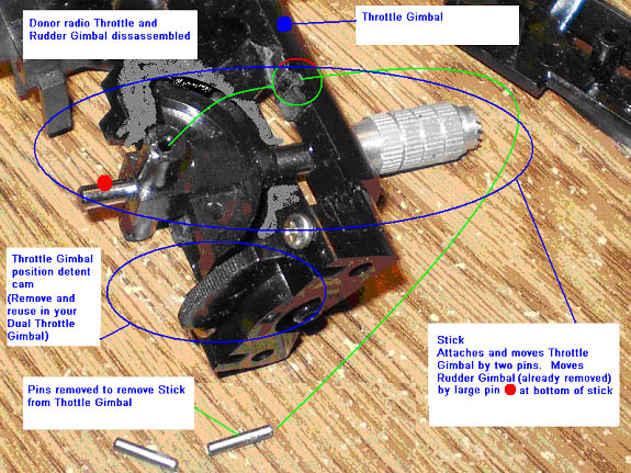
See graphic below showing one of the sticks being removed from the Donor Tx throttle and rudder Gimbal Assy (partially disassembled.
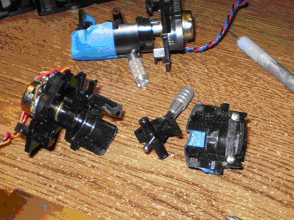
One Donor Stick fully removed.
I then laid out all the parts to decide how they would best fit together. A little roughing up of the future attaching surfaces on the sticks and gimbals was done with the Dremel tool, holes were marked and drilled into the gimbals to accept the lower end of the sticks, and minor relief was routed into the sides of the sticks where they would nest into the gimbals (see pictures).
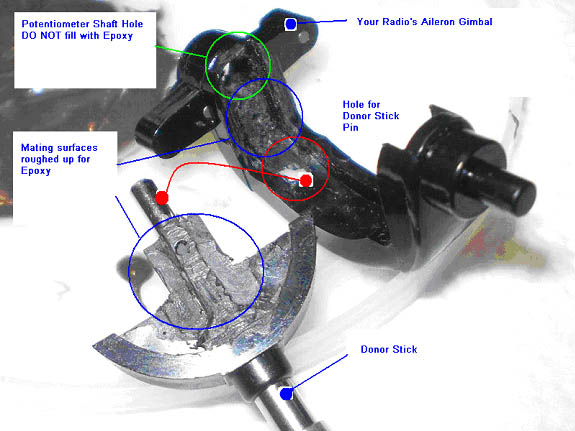
I trimmed off the standoffs from the sides of the sticks as they needed to be re-located slightly upwards to provide "cross-support" between the throttle gimbals to keep the gimbal-weight from levering the potentiometers shafts and possibly causing the internal electrical contact from being opened and thereby causing loss of control of the respective motor. The had to be mounted at the axis of rotation of the sticks/gimbals once they were assembled, or else they would move in the same direction together with no separate control motion being possible.
To Be Continued...
 Feel
Free to ask questions about this section, or any part of this site by emailing
here.
Feel
Free to ask questions about this section, or any part of this site by emailing
here.

Back to Construction Articles
281
Version 1.00 4/08