
I have been asked from time to time to show the processes involved in making a master pattern used for a RTV rubber mold. In this article, I will take you through the steps I take in making a pattern for a Baltimore class 8" turret from scratch. Obviously, there are many different ways and materials to do this, so I present this as a way, not the only way.
Click on the images to enlarge them, and use the back button on your browser to return to this article.
To make an accurate pattern, you have to start with accurate information. Sometimes, you just have to use what you have, and take your best guess, but if you look around, you can find a surprising amount of information in libraries and on the Internet.
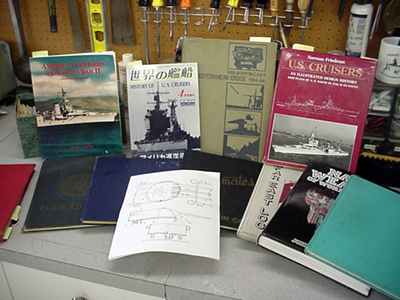
In this case, I used plans from the Floating Drydock , standard reference books on US cruisers, and a number of cruise books for the various cruisers. A variety of photos from different angles will give you the true shape of the part, and will let you catch subtle details that plans alone may not illustrate completely. Additionally, many parts of Naval ships are modified as their career progresses and good photographs will documents these changes so you may capture the part at the correct point in time. In this case, I am building a turret master that will be for late war and 1950's Baltimore class turrets, so turret range finder hoods will not be needed. Later, I will modify a production casting to make a master for the earlier version of the turret that had the hoods.
For many solid shapes, I use Plexiglas blocks as the basic material component. It is easy to shape with wood and metal working tools, sands well, and takes paint superbly. Unlike wood, it needs no filling before priming, and of course, there is no grain to deal with. It's main disadvantage is a propensity to develop surface cracks if overheated, so power sanding should be done lightly and with a gentle touch.
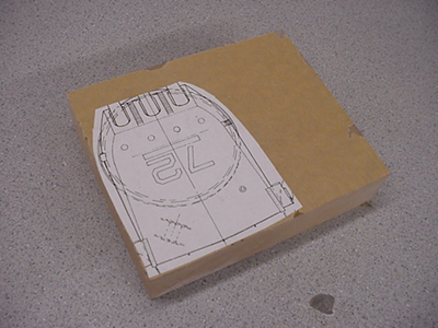
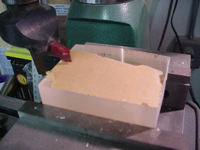
I make a copy of the plan (in this case, I scanned it into the computer to print out additional copies), and attach the copy to the blank plexiglass block with a strong spray adhesive. 3M # 77 adhesive is one such product, but there are many to choose from. Just about all those rated as a "permanent" adhesive will do the job, which is to keep the plan from shifting on the block during the shaping process.
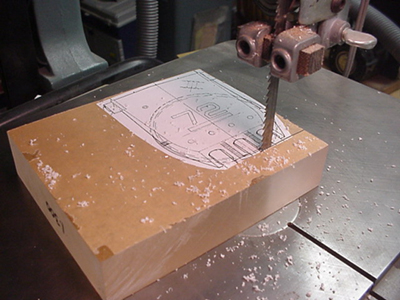
The rough cutting is done along the largest view, in this case the plan view. If needed, the cut off pieces can be retained and temporarily reattached to the block is a complex profile is to be cut as well - this would be the technique I would use if making a pattern of an airplane fuselage, for example. For this turret, one rough cut around the perimeter was sufficient to establish the basic shape.
Once the turret shape was roughed out, it was brought over to the Mill/Drill for squaring up and to begin the precision shaping process.
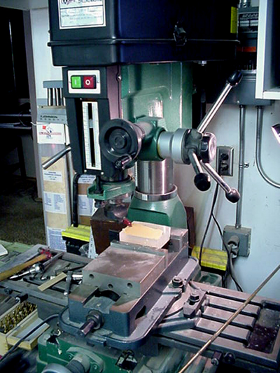
My Mill/Drill is from Grizzly Imports, and is a very useful machine indeed. In size, it fits the niche between ordinary drill presses and full scale Milling Machines. It has more than enough power for any common model material, and is very accurate. Although it has not completely supplanted my Sherline machinery, I find myself using it quite a lot, especially for larger parts.
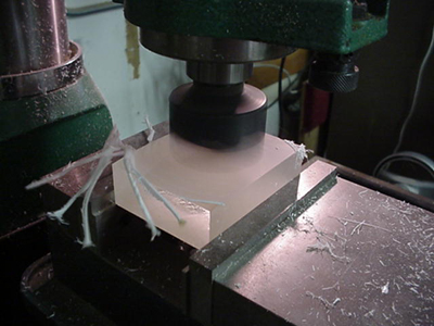
The first process is to flycut the top and bottom of the blank to insure they are parallel with one another. This is very important as every other process is dependent on referencing off these surfaces.
Please read and understand how to use your tools before attempting this process. Use extreme care to ensure that your flycutter bit is securely mounted in the holder, as a cutting bit flying through your work shop at extreme speed would be very hazardous!
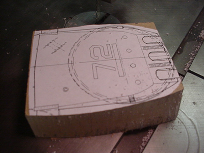
Once the top and bottom are parallel, then the flycutter are use to establish the outside dimensions of the part. I always leave a few thousands extra material for the final sanding to size.
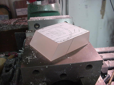
Cutting the turret face angle was done by grasping the turret by the (now square) sizes, tilting it to the proper angle, and then locking it in the vice. If everything has been done accurately to this point, the turret face cut should be parallel as well, with no tapering to one side. In this case, fortune smiled on me, and it was right on the money!
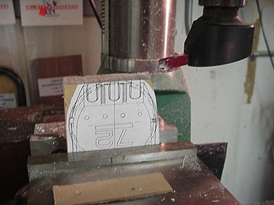
This can be a tough step, but a few tricks made it a bit easier. First, I extended the layout lines from the drawing at the top to the front of the now milled turret face. These lines were double checked to make sure that they were the correct distance from one another and the turret edge. I then plotted out the top and bottom of the openings. Because milling cutters are made to standard sizes, you will often have to choose one that is as close as possible to the actual scale dimension. In this case, that meant it was about .005 oversize, which was acceptable as this style of turret had heavy canvas bloomers which overlap the opening in any event.
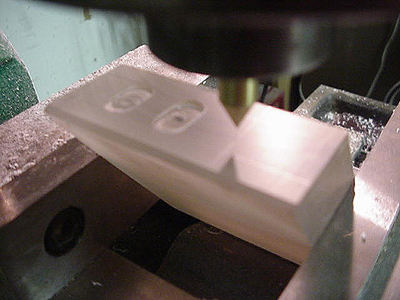
This somewhat blurry photo shows a neat little trick I learned from a book on machining to help line up the cutter to the layout line. I took a brass rod the same diameter as the cutter body, and turned it in a lathe to a very sharp point. When inserted in the mill cutter collect and lined up over the line, it will bring mill exactly over the center of the cut. By not moving the cross slides, raising up the milling head and inserting the cutter for the pointer, the cutter is exactly lined up for the cut.
The first cut is carefully made up to the layout lines and down to the depth your desire. The dial readings on the mill cross slides are noted, and then the subsequent cuts are made with the dials only. This ensures that each slot with be the same length and depth as each other.
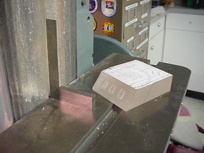
Before final sanding on the belt and disc sander, I use a machinist's square to check and make sure that the table is still 90 degrees to the belt. I learned this lesson the hard way! Any machine that produces vibration will need this check if accurate work is needed.
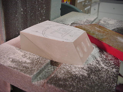
The turret after sanding. The back is straight forward, but the sides of this turret have a knuckle from the rear turret roof to about half way on the bottom. This can be rough shaped with power tools, but the final shape has to be done with hand tools. No easy was to do this, just a lot of checking to make sure you don't loose the line at the top or bottom.
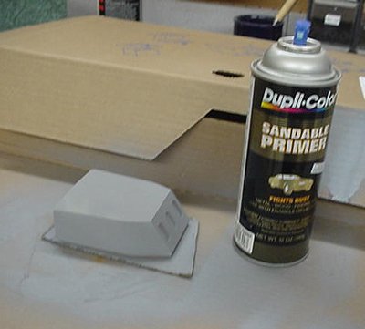
Once the turret is close to the final shape, priming will help fill in the sanding scratches, and act as a guide to the final shaping process. This is done my hand, with rigid sanding sticks to ensure that edges are not softened.
My plan is to update this page with some shots of the finished turret, and also the process of backdating the pattern to the early war design. Stay tuned!!
 Feel
Free to ask questions about this section, or any part of this site by emailing
here.
Feel
Free to ask questions about this section, or any part of this site by emailing
here.

Back to Construction Articles
283
Version 1.0 10/01