
From Hull to Lake:
Turning your fiberglass hull into a working model
By James Mousaw
Note: Click on any of the photos to see a larger version
A lot of people have asked me to post how turn an empty hull into a running model, so I decided to document this build to answer a lot of questions.
Now, I do things a little differently than a lot of modelers, so some of this might seem a little out of the ordinary.
I can’t get into model specific details; for example the spacing of the beams, how many should be installed, and shaft spacing and height. All that is pretty specific to your particular model.
The general rules of thumb I use are these:
Step one: Installing beams
Prep the inside of the hull by sanding or grinding anywhere you want glue to stick. If you don’t do this, it is likely your part will pop off eventually, even when stressed.
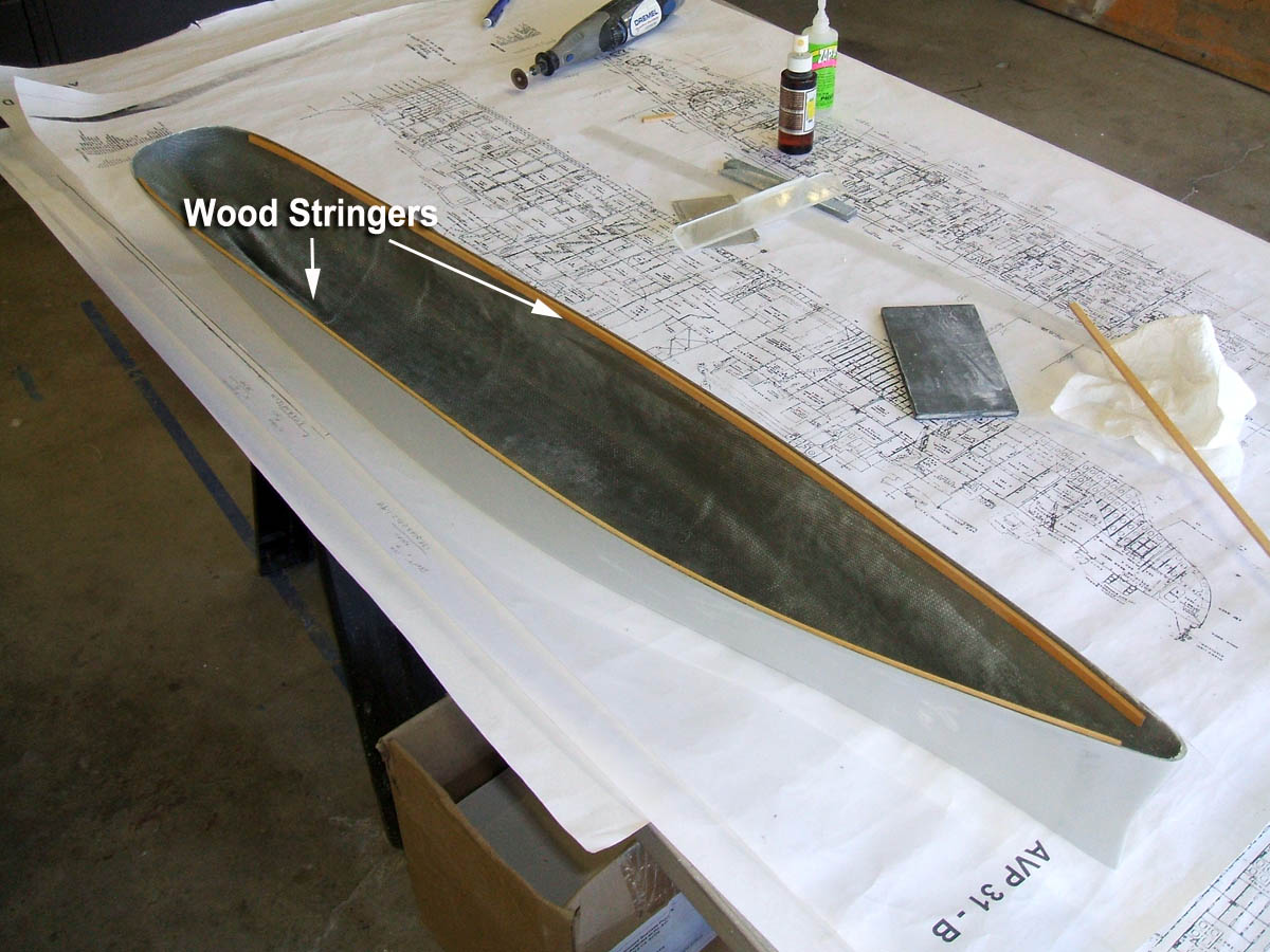
The first parts to be installed are the side stringers.
They give the hull a little rigidity and prevent building a wave into the hull sides.
Click to see a larger version
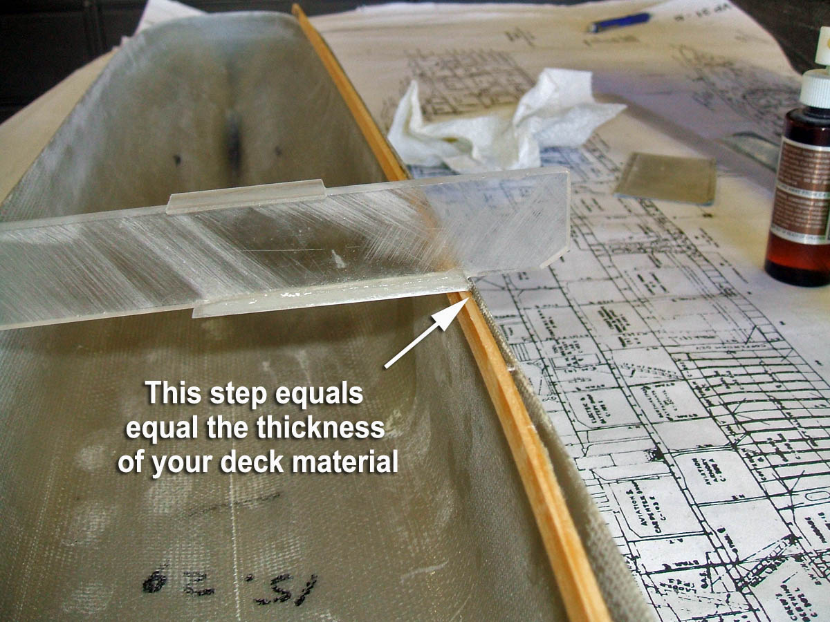
To install these you need to build a jig that will set the top of the stringer below the deck edge by the thickness of the material being used for the deck.
The deck is set inside the hull, not on top of it. It’s easier to fill the seam between deck and hull edge than try to keep the deck edge from cracking and showing on the hull side. It also helps with making the waterway.
Next the beams get installed.
Set the hull width by pulling the hull in to the correct width and hold it there with tape.
More rarely the hull will need to be pushed out by the beams, which is even easier.

Then use the jig to set the height the same as the stringer.
Start from the center and work out to the bow and stern.
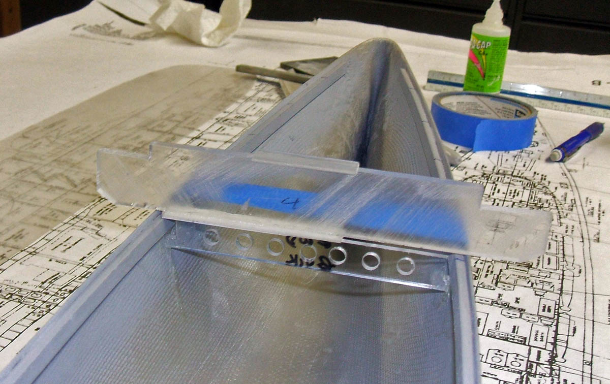
At this stage, I only put in most of the horizontal beams leaving the longitudinal beams out to be installed later. This helps with installing all the internal components.
Note the lightening holes I drill into the beams to keep weight down; for most models you want to keep the weight above the waterline as low as possible.

Step two: Installing the shafts
This is an area where my techniques are significantly different than those used by most modelers.
I like being able to remove the stern tubes for maintenance or repairs, so I use both an outer support tube (Holding tube), and an inner stuffing tube (Stern Tube).
Here are all the parts that I use to install shafts.
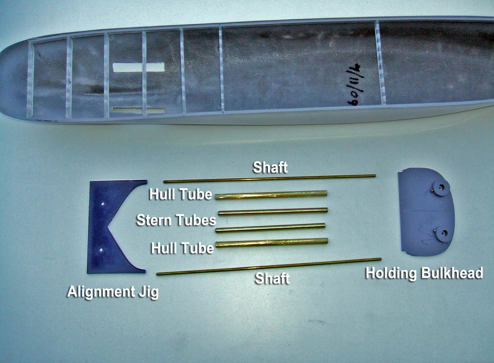
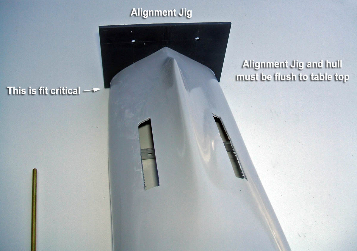
Using the plans I build an alignment jig. This jig will set the height and spacing of the shafts.
Build the jig to match the stern contour and is flush with the top of deck.
It is usually pretty easy to get the dimension from the top of the deck down to the center of the propeller shaft where the strut arms end.
This gives you a common datum point for both the internal and external height of the shaft.
Drill holes in the jig that correspond to the height and spacing from your drawings and are the same diameter as the shafts.
Then cut in the openings in the hull for the stern tubes and tack glue the jig in place.
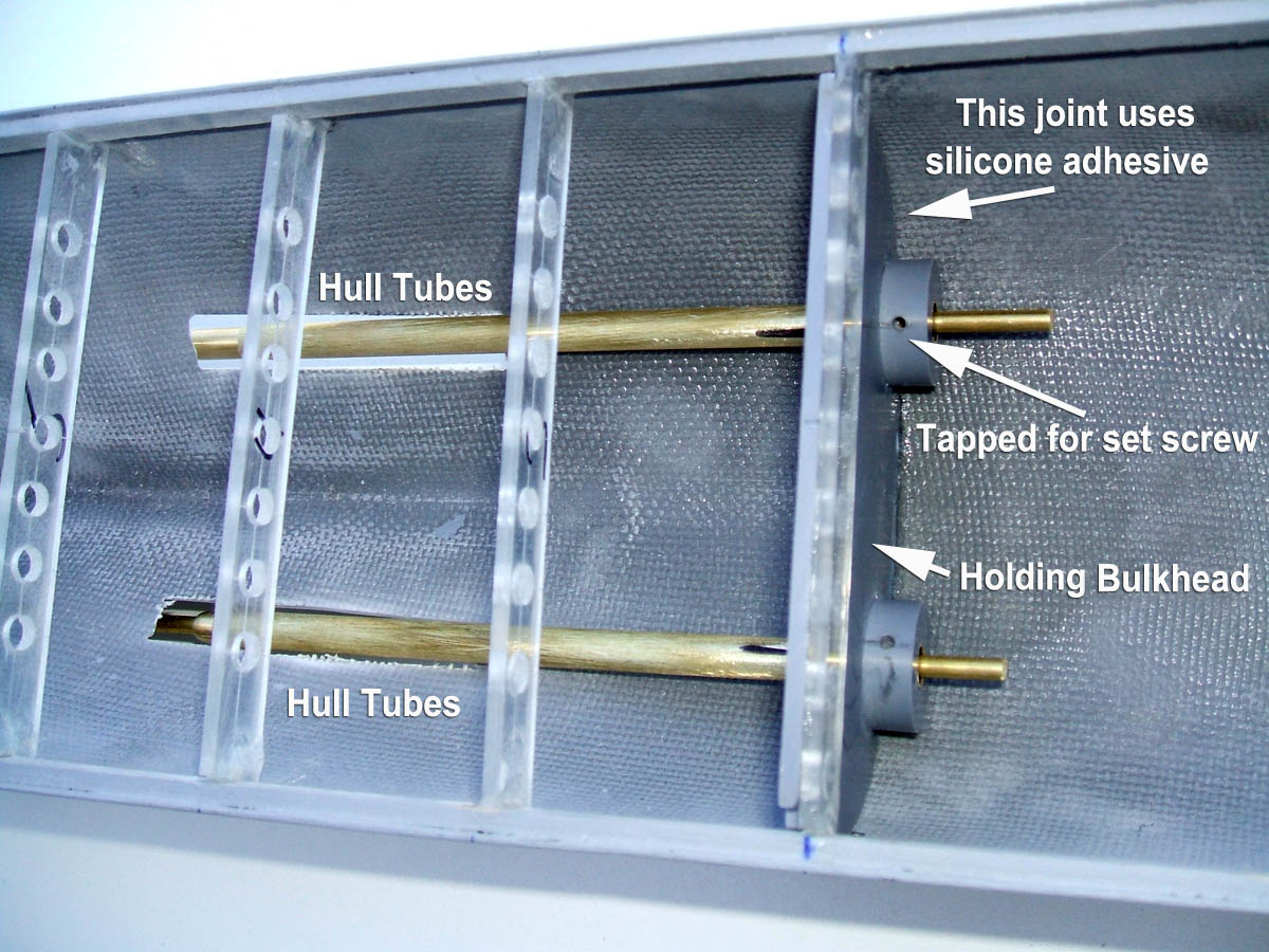
Next the holding bulkhead is installed.
I glue this in place with super glue and seal both sides with clear silicone.
That makes this a watertight bulkhead, and the silicone won’t crack from vibration.
Push the hull tubes and stern tubes into the holding bulkhead
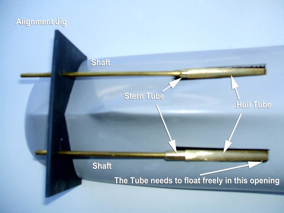
Place the shafts into the alignment jig.
Make sure that the shafts also extend out the stern tubes inside the hull.
Here you can see the stern tubes (rounded ends) sticking out of the hull tubes
Everything should float freely at this point.
If the tubes contact the hull, it could cause some misalignment.
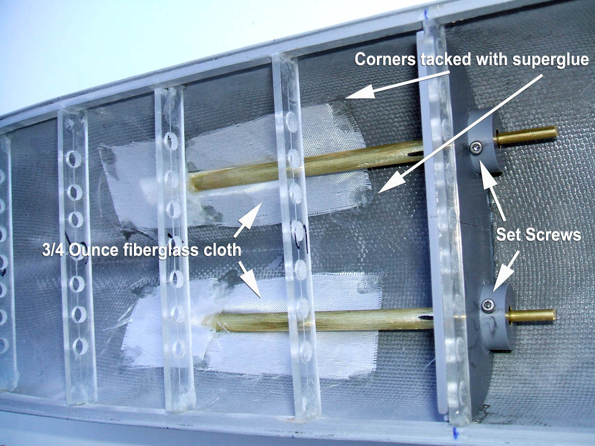
Next, cut some pieces of fiberglass cloth to cover the holes. Put one under the tubes and one over them then tack the corners down with superglue.
Check the position of the hull tubes; this is the time to be extra careful with the alignment..
Make sure that the ends are flush to the end of holding bulkhead. Tack the hull tubes in place with super glue.
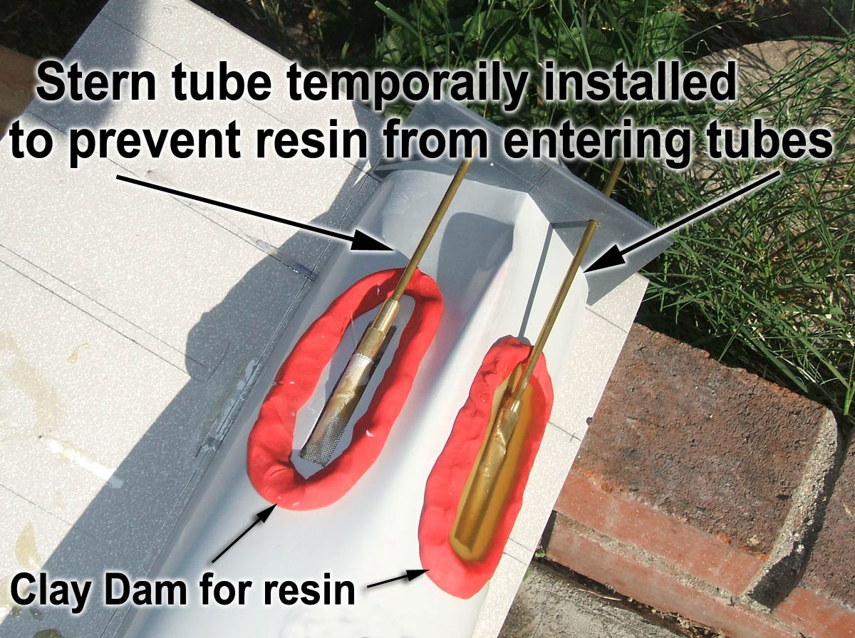
Build a clay dam around the holes, and pour in fiberglass resin.
Leave the stern tubes exposed out of the hull tubes.
You will get resin on the stern tubes but it is much easier to remove than in the stern tubes.
Make sure the resin doesn’t get into stern tube opening. It is very difficult to get it out.
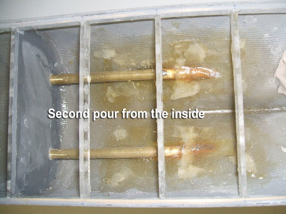
When the resin has hardened, turn the hull over and resin the inside of the hull.
When the resin has cured then turn the hull back over, remove the shafts, alignment jig and stern tubes.
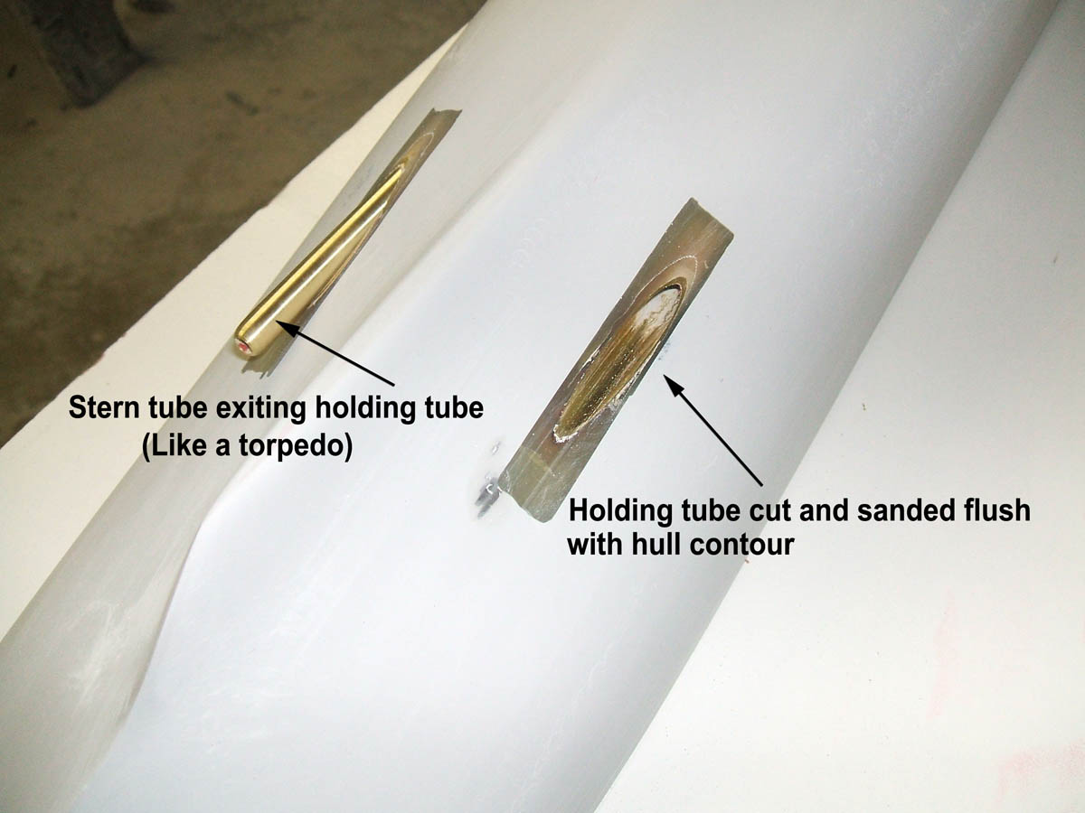
Then cut away the hull tube and resin and sand until they match the hull contour again.
It should look like an open torpedo tube, and when the stern tube is put back in it looks like a torpedo exiting the tube.
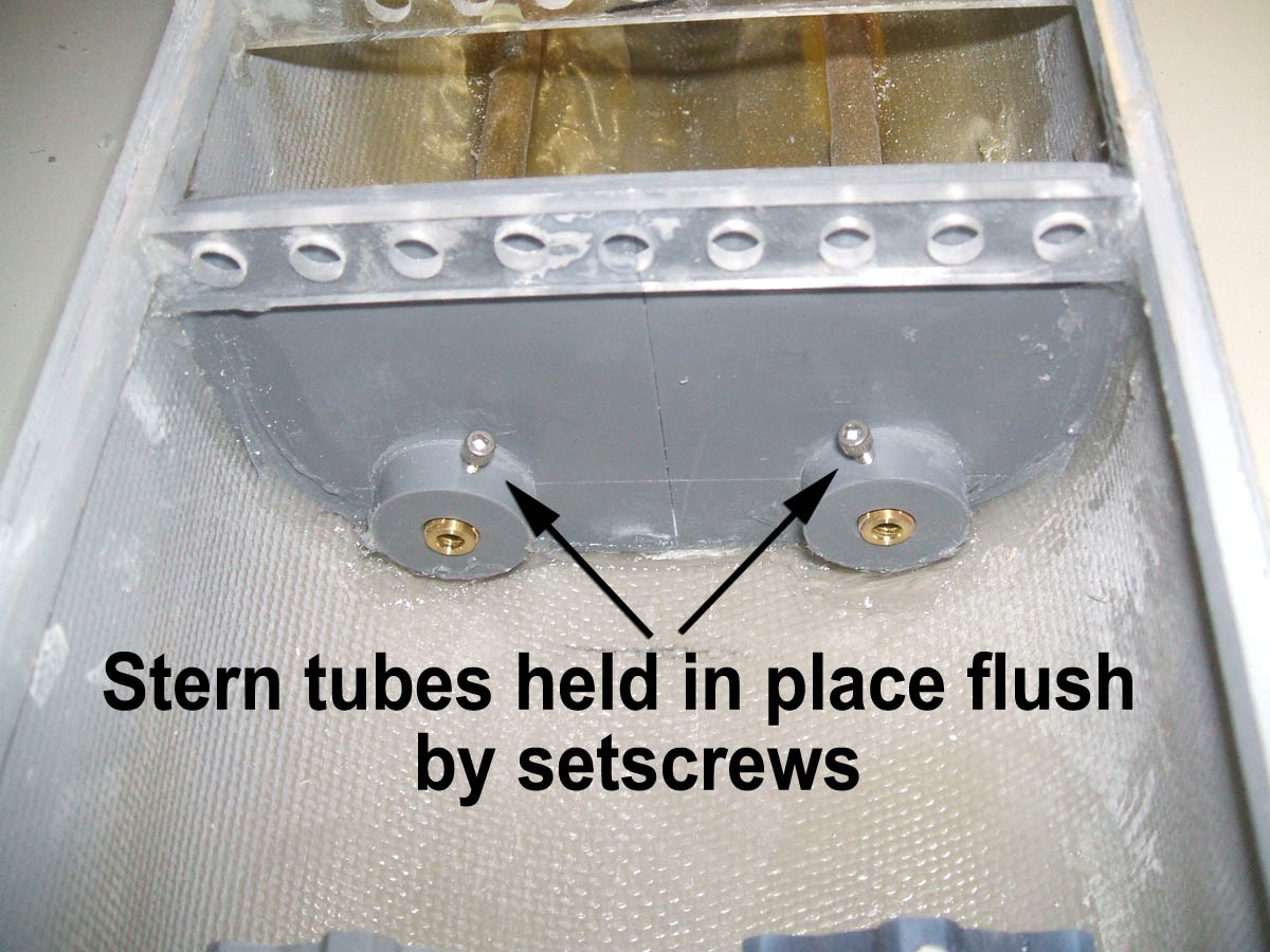
Put the stern tubes into the hull tubes and lock them in place with setscrews in the holding bulkhead.
First, check the shaft by rolling it along a known flat surface, such as a granite counter top, glass table top or a machine tool surface, such as a table saw. I
f you see any wobble at this point replace it.
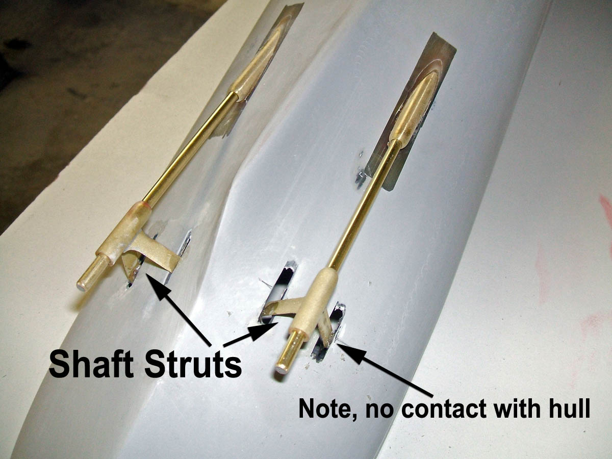
Cut the holes for the shaft struts and let them hang from the shafts. Again they should float freely to avoid misalignment.
Spin the shaft to check the runout. If there is too much, replace the shaft – this is the final check for shaft trueness,
If you can see the strut move around then there is too much runout.
This is the critical point of alignment. Try and get everything as true as possible.
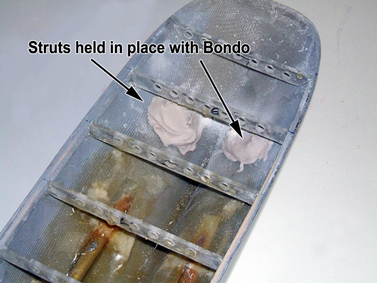
When they are properly aligned, tack them in place with super glue. This is just to hold them in place so you can turn the hull over and Bondo the struts to the hull.
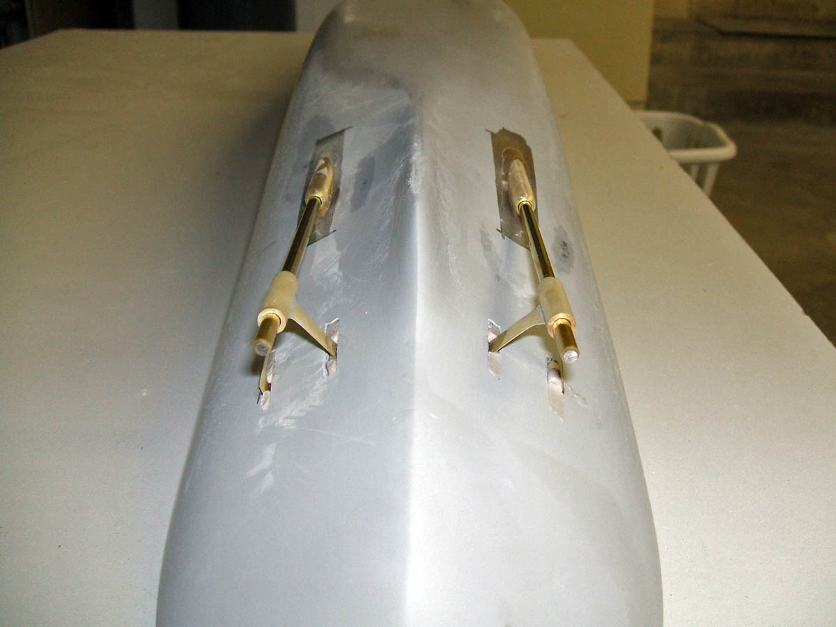
Here are some pictures of the end result.

End of Part 1......to be continued
Feel Free to ask questions about this section, or any part of this site by emailing here.
Go
back to Construction Articles.

Version 1.00 11/09
![]()